Leaderboard


Popular Content
Showing content with the highest reputation on 06/07/15 in all areas
-
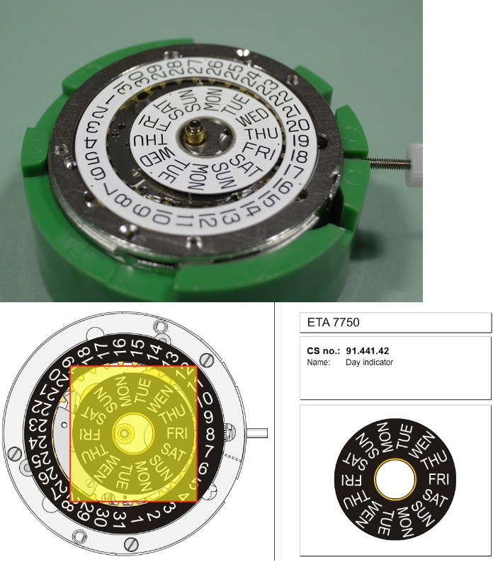
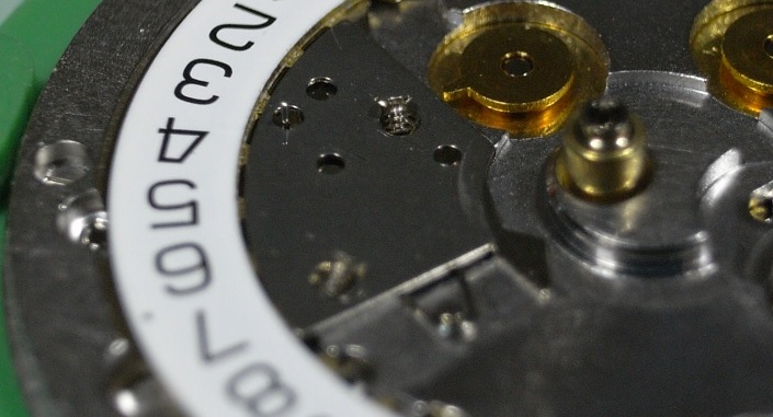
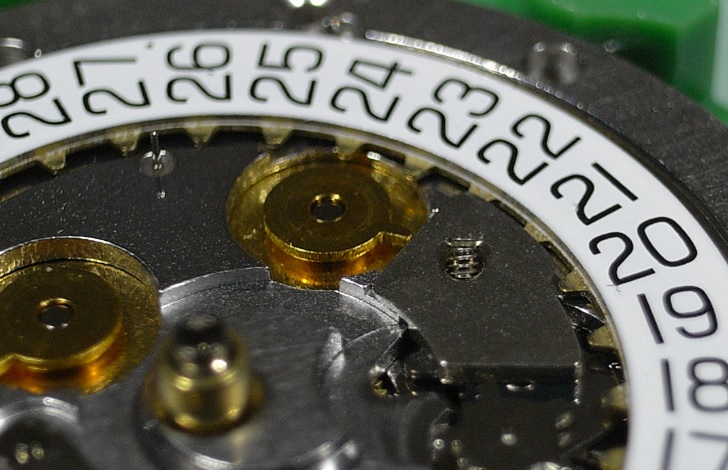
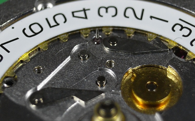
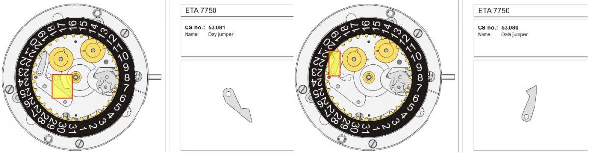
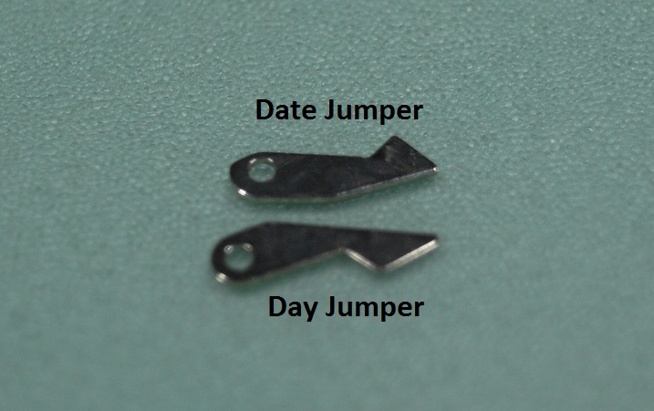
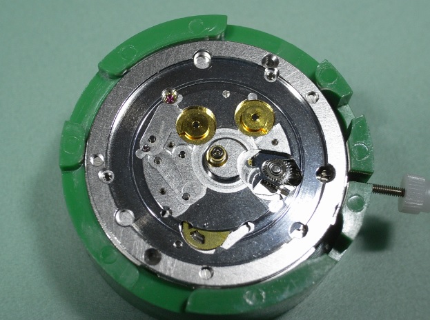
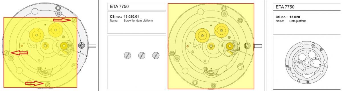
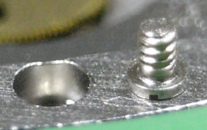
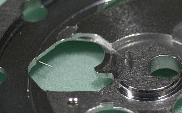
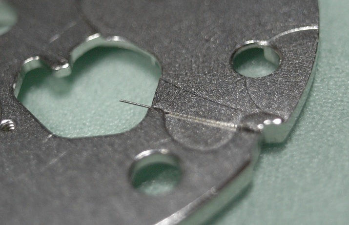
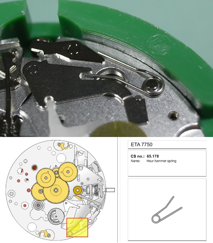
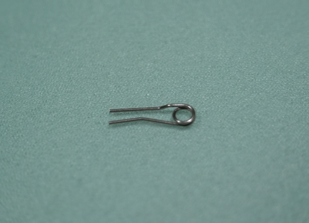
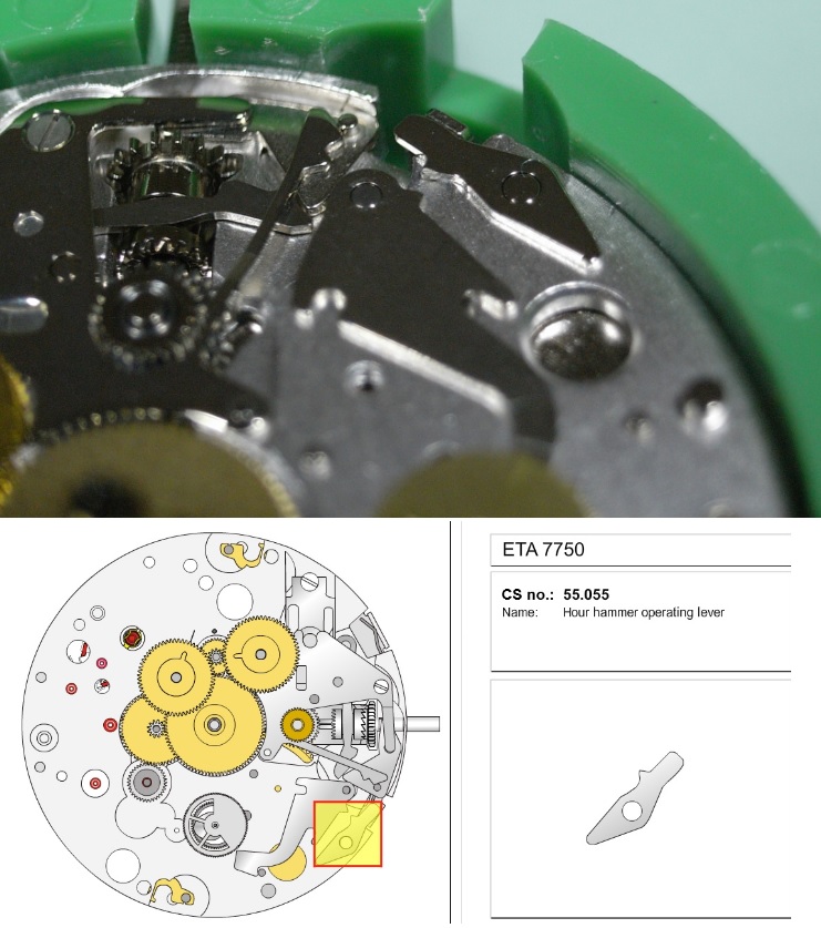
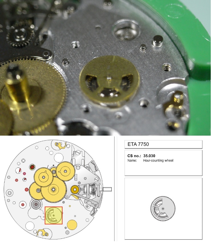
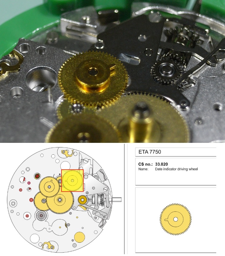
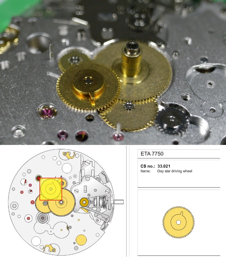
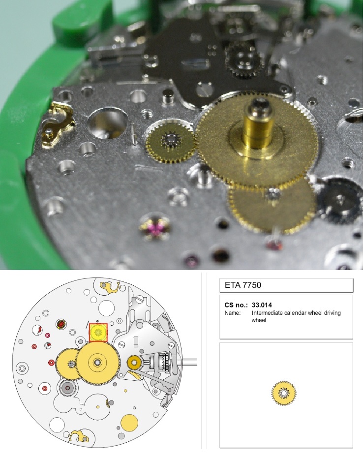
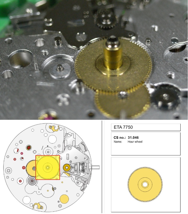
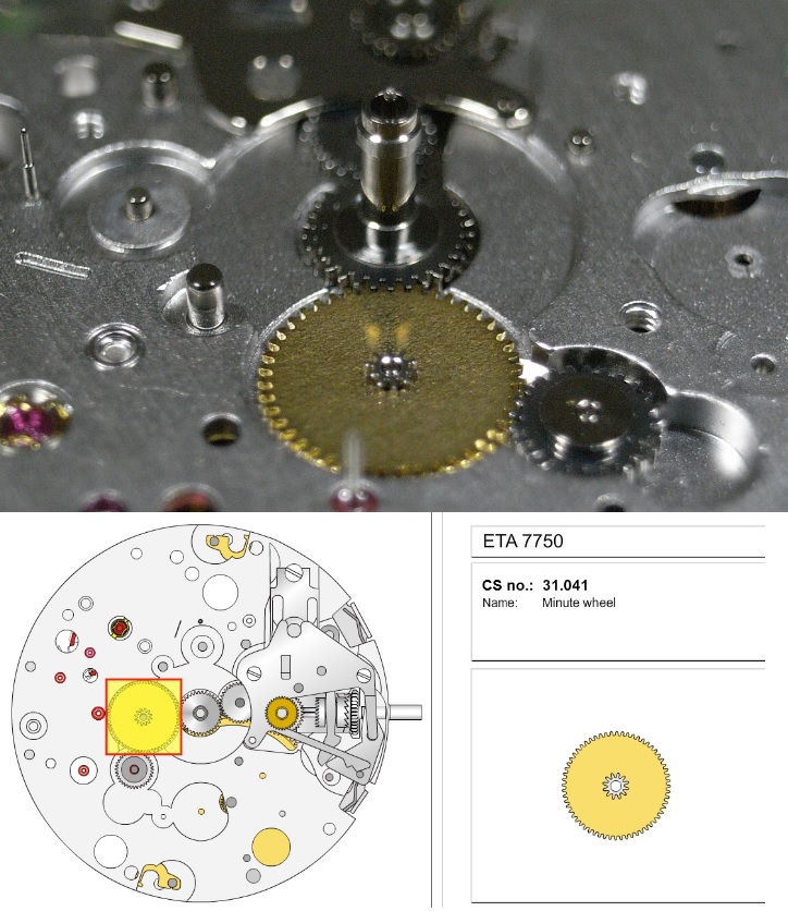
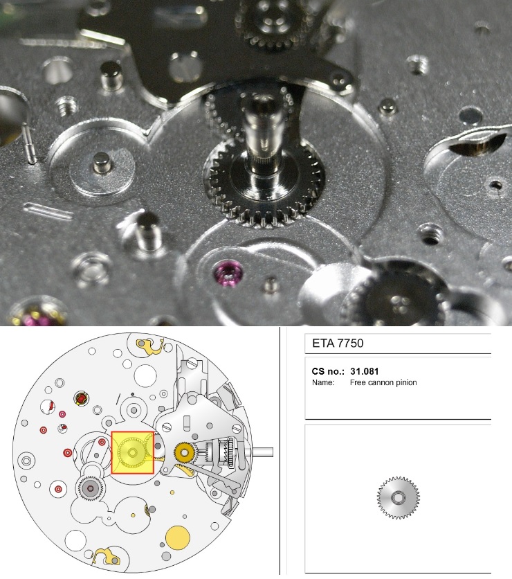
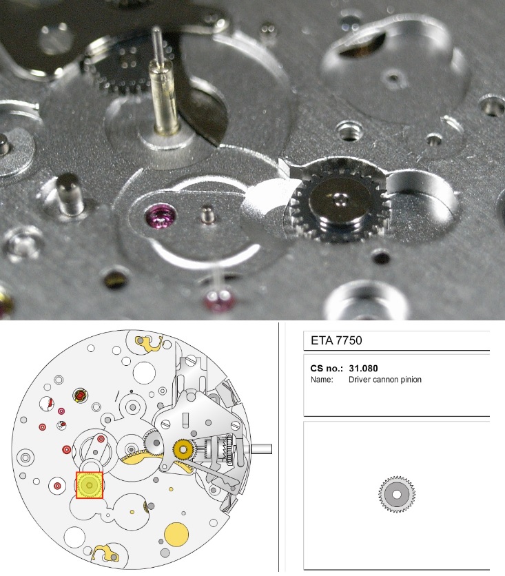
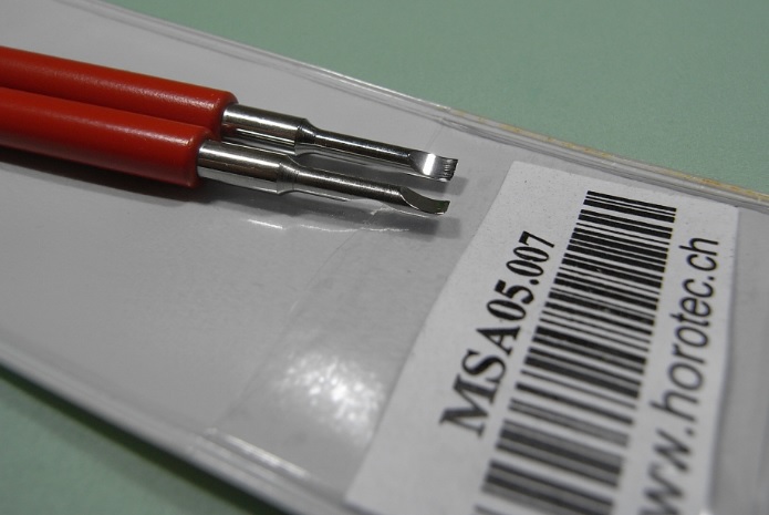
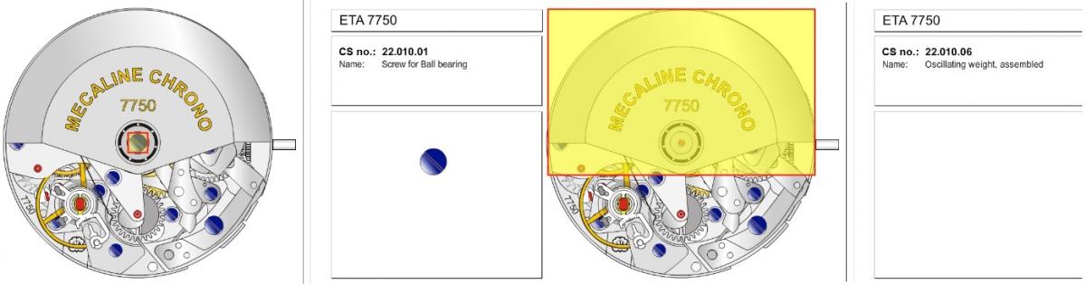
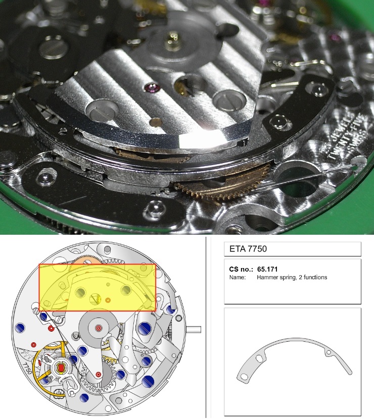
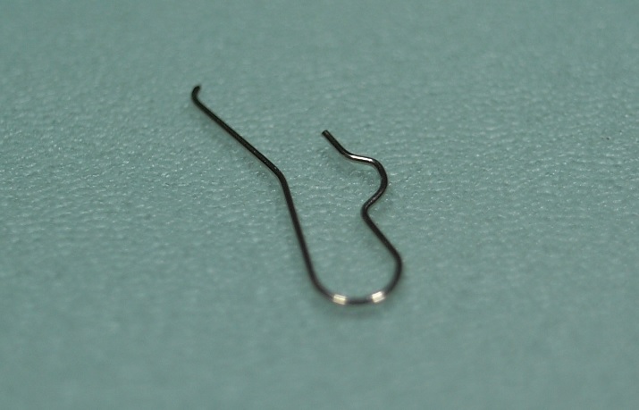
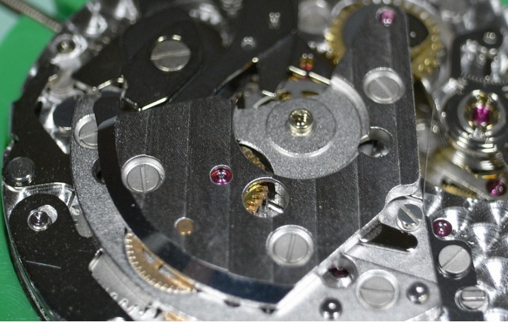
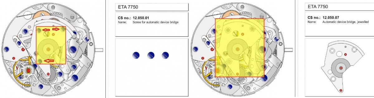
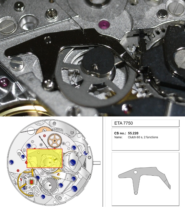
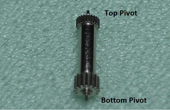
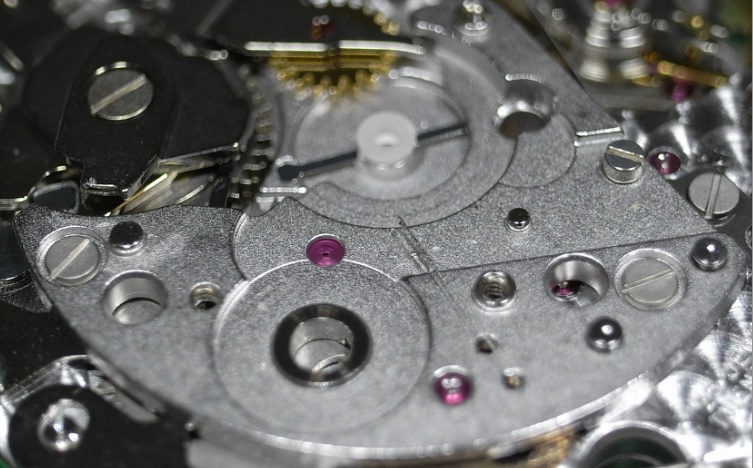
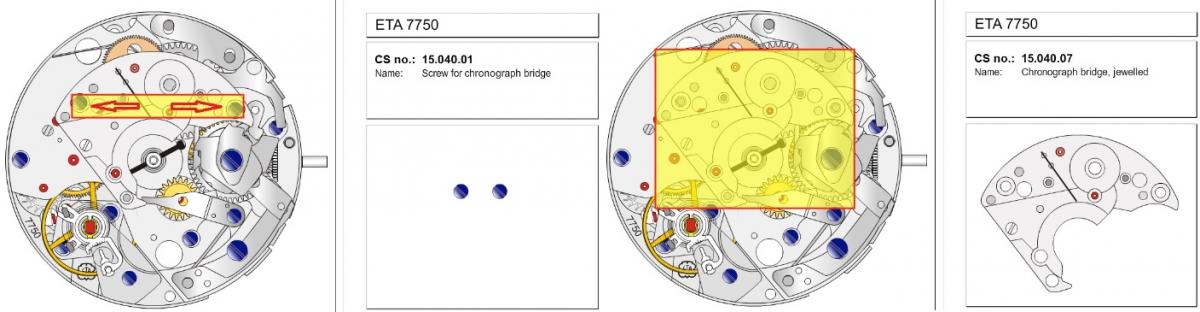
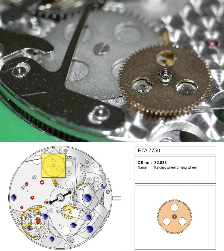
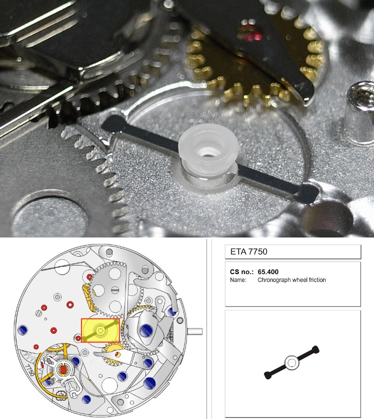
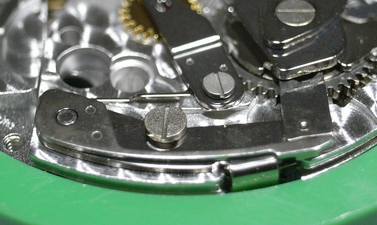
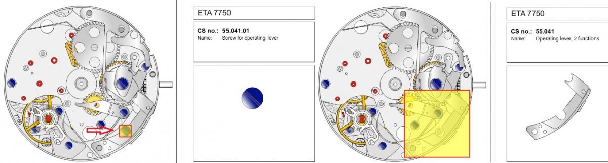
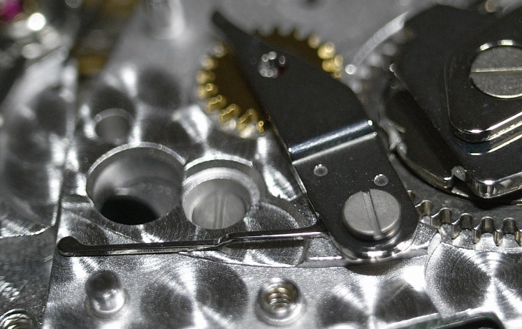
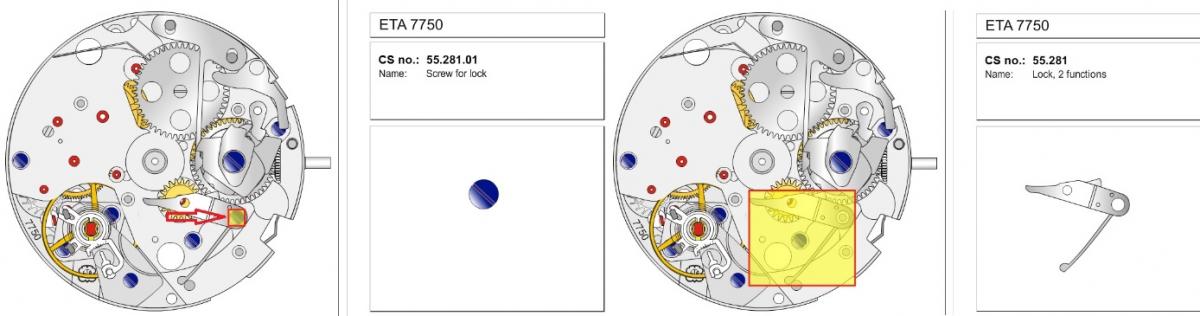
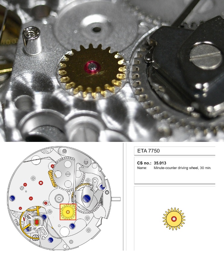
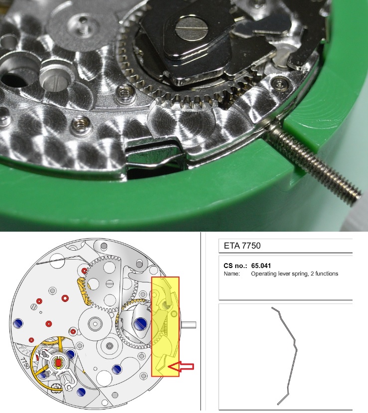
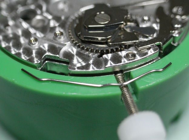
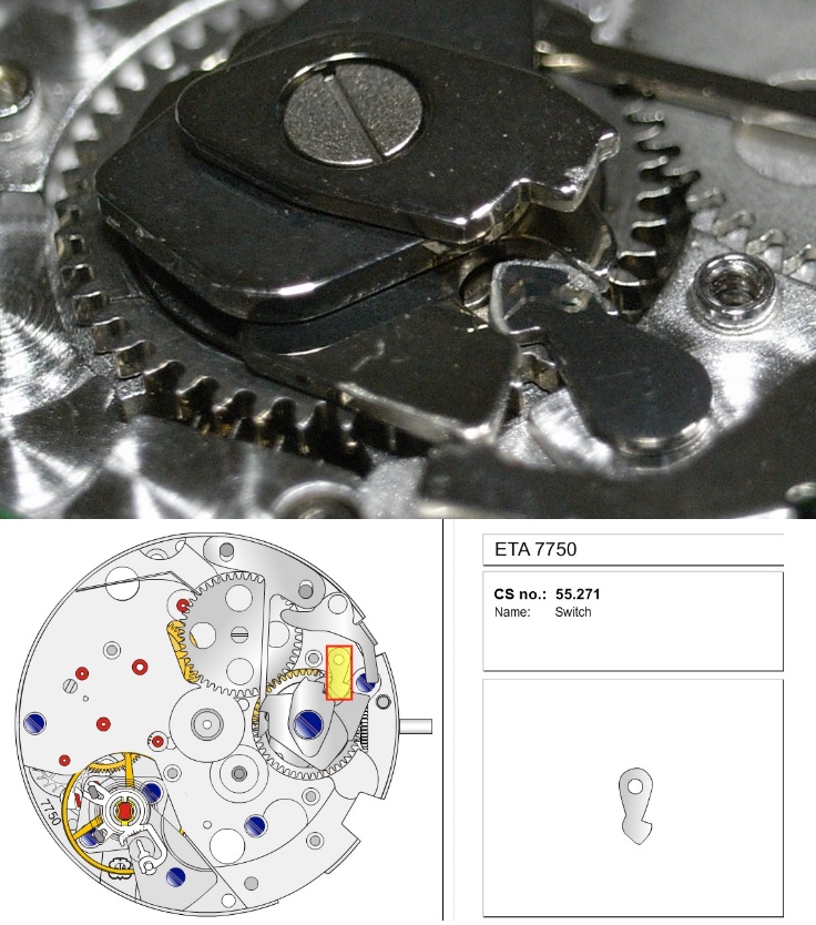
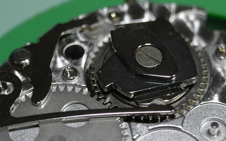
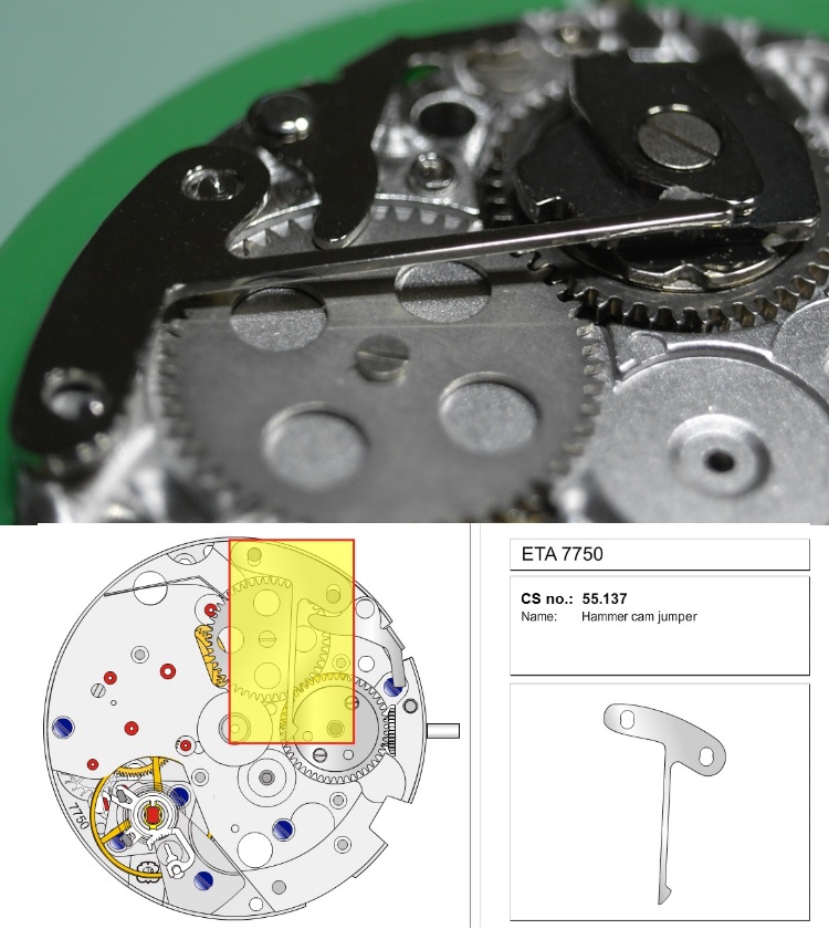
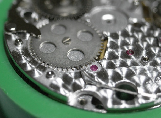
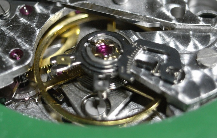
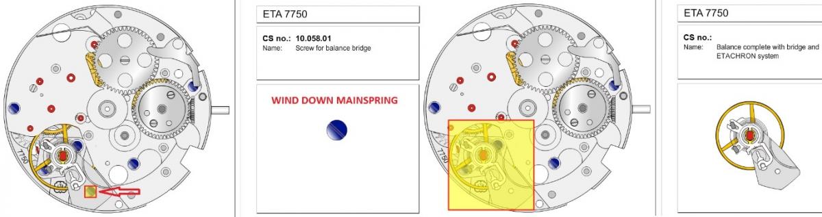
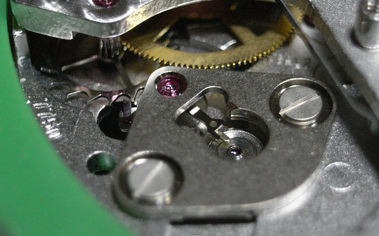
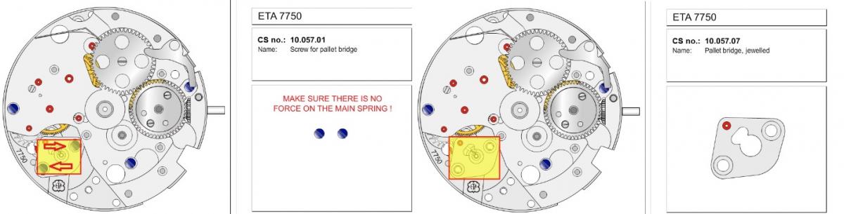
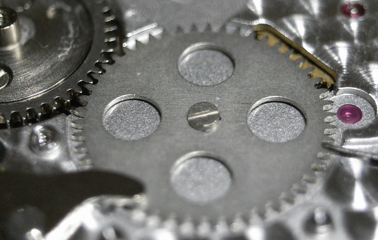
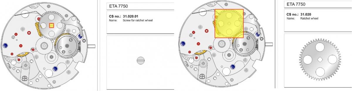
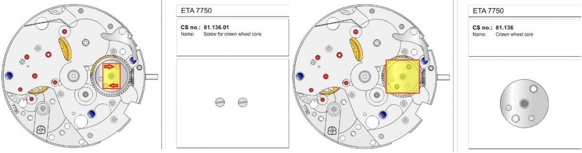
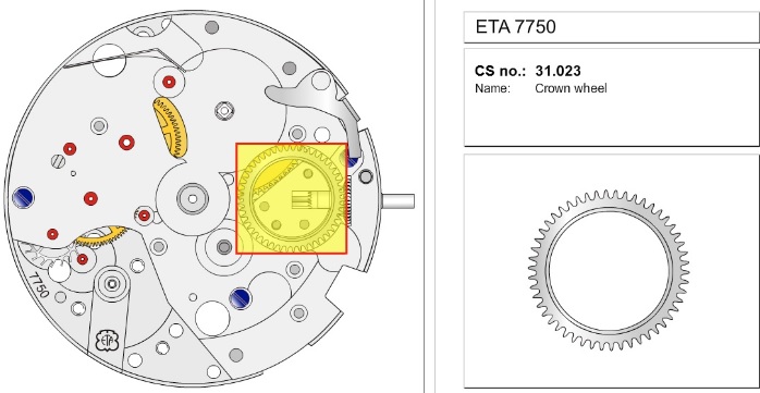
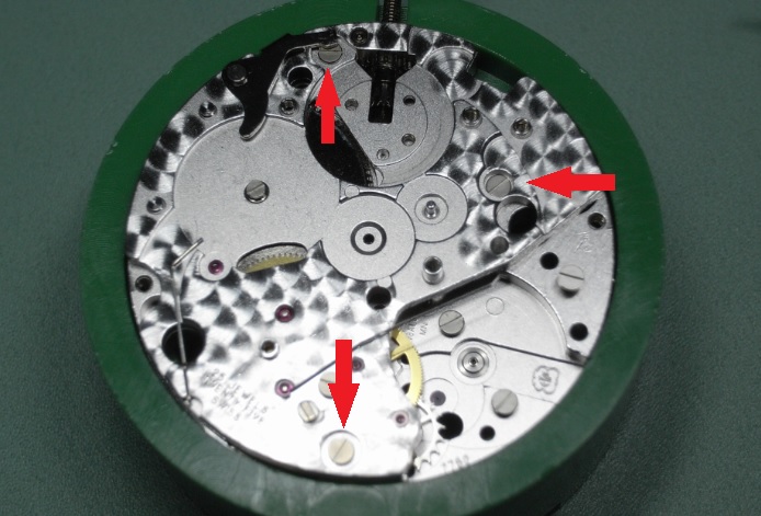
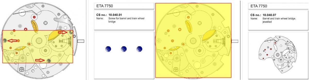
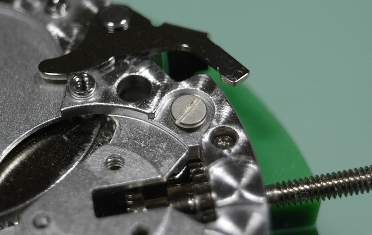
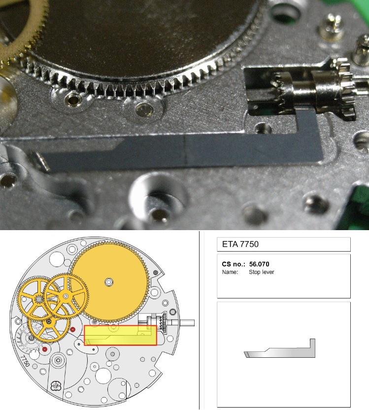
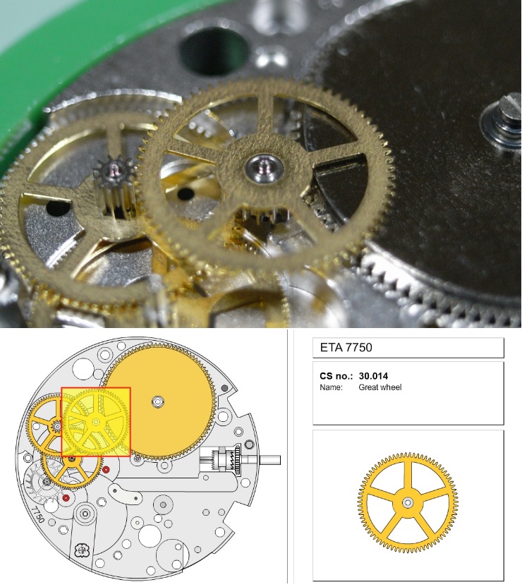
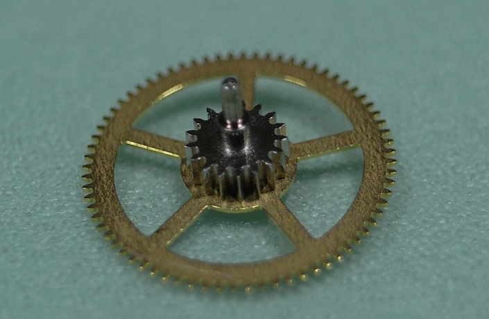
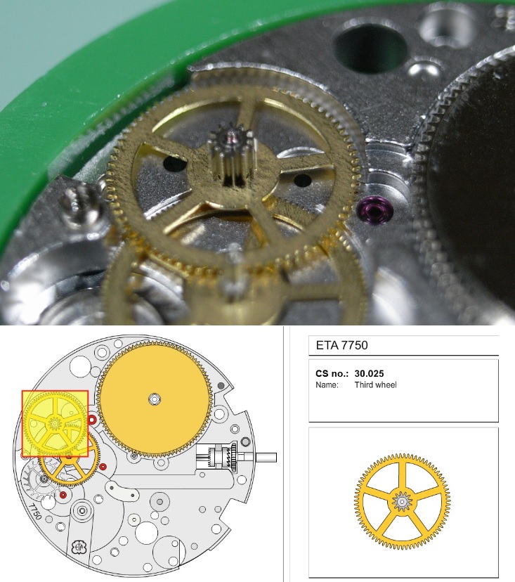
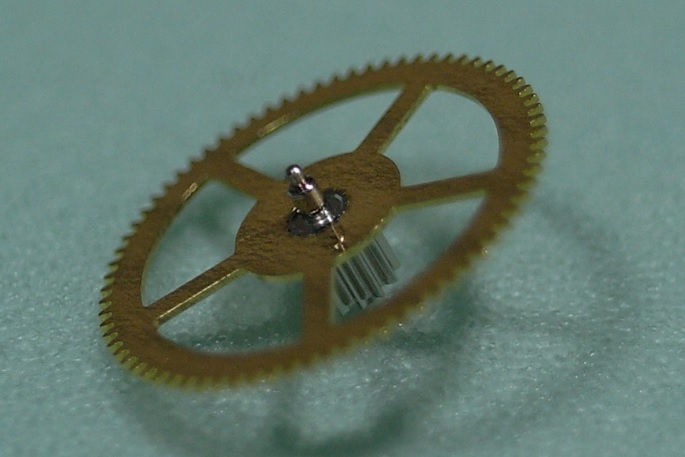
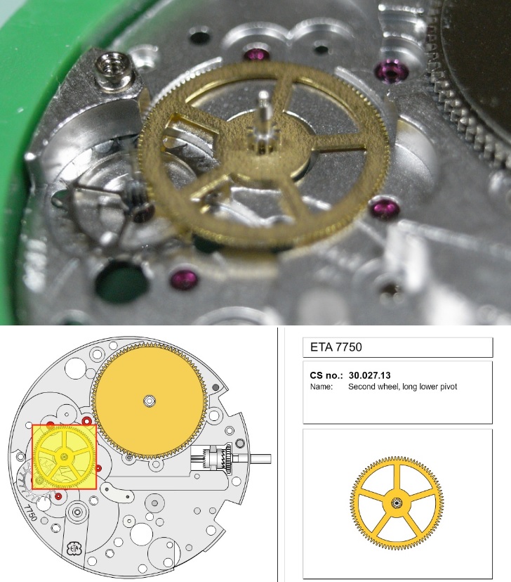
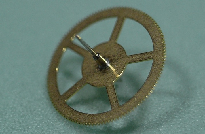
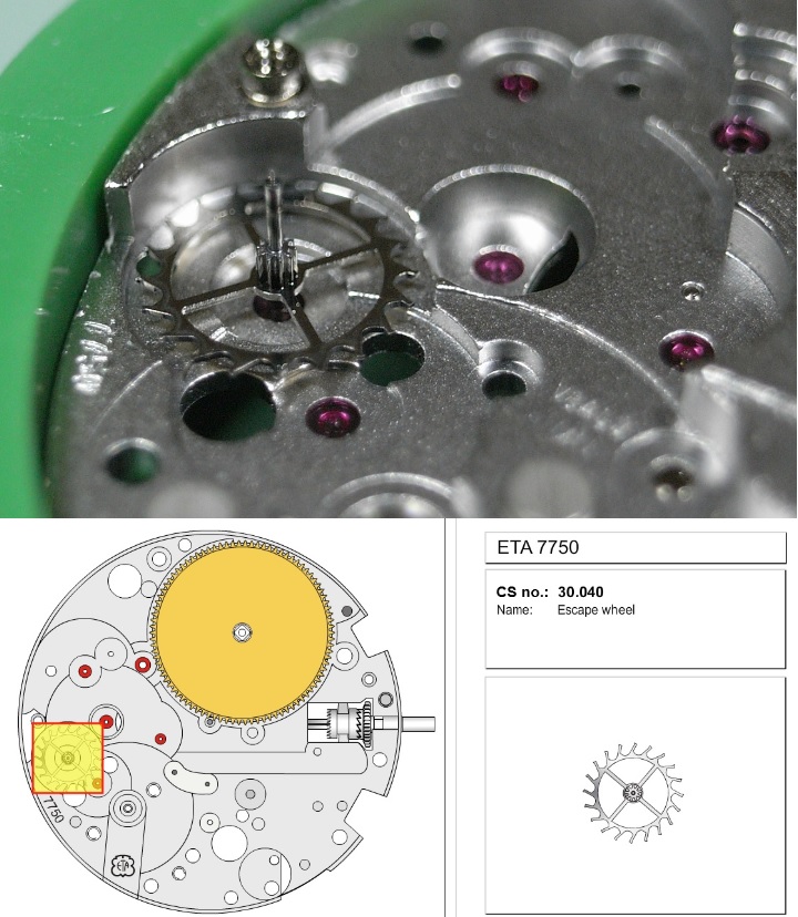
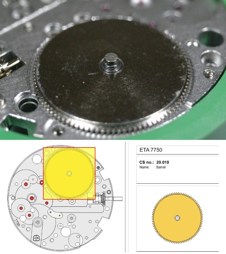
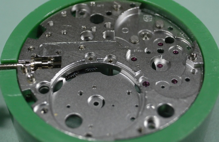
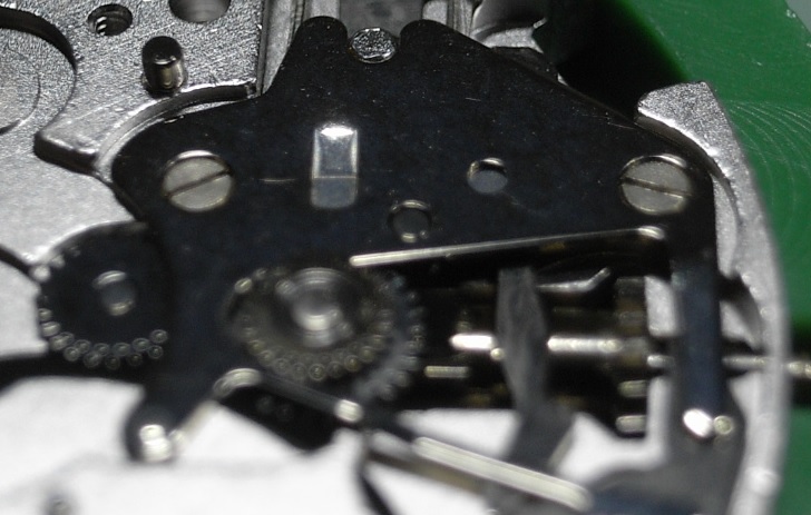
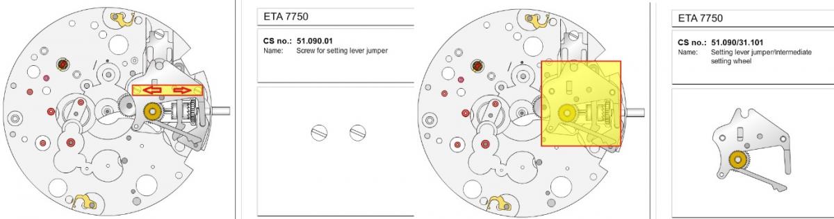
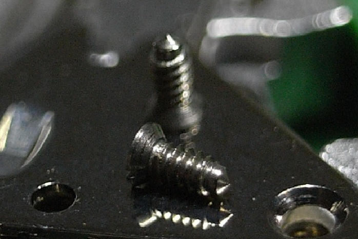
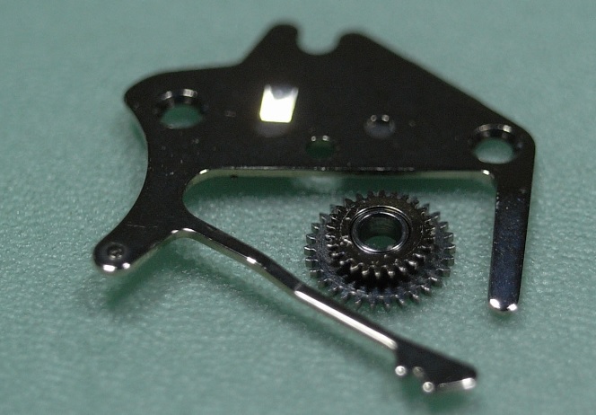
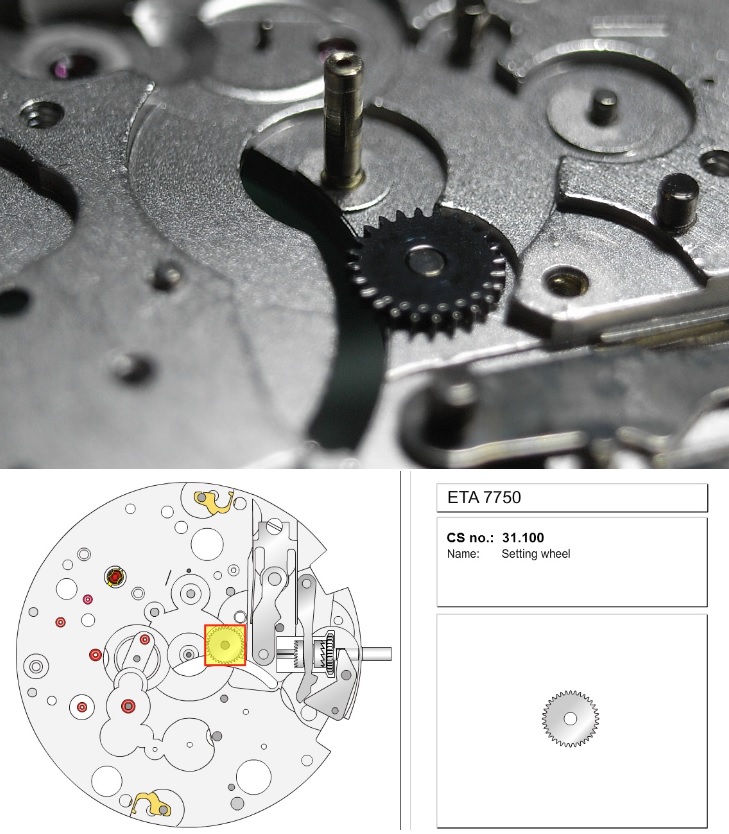
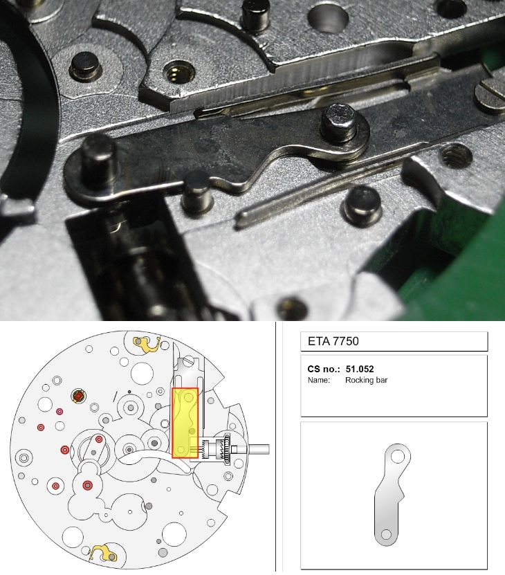
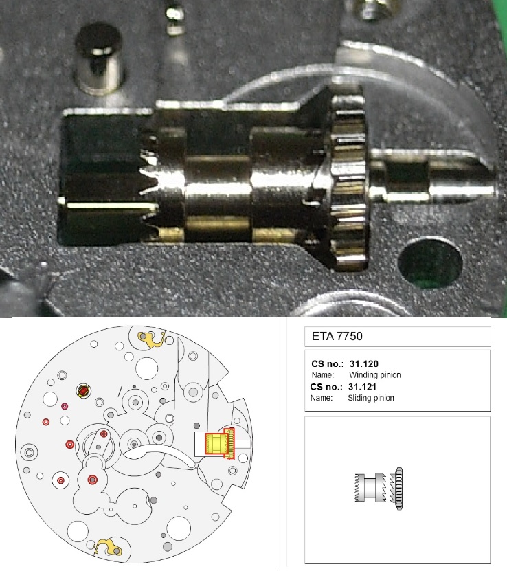
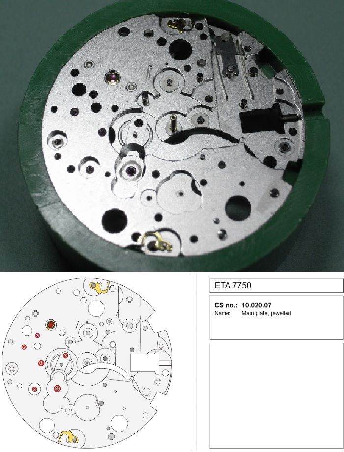
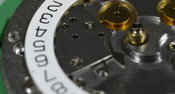
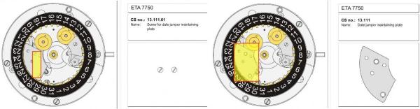
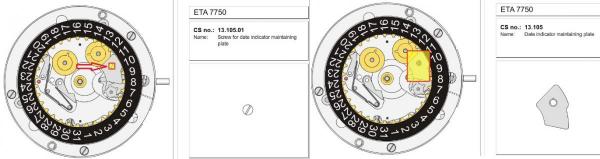
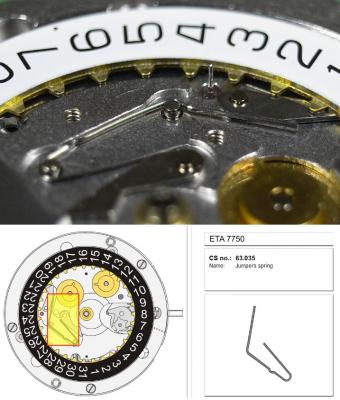
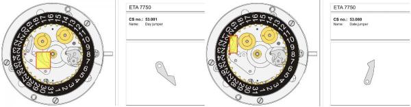
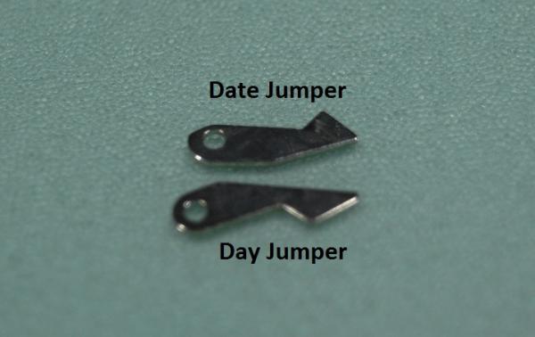
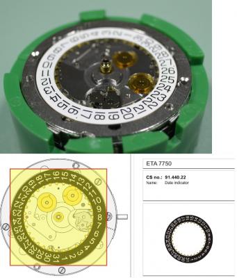
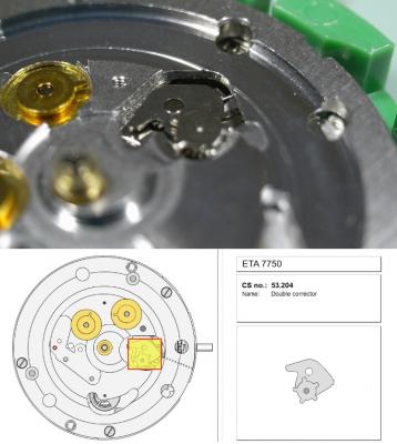
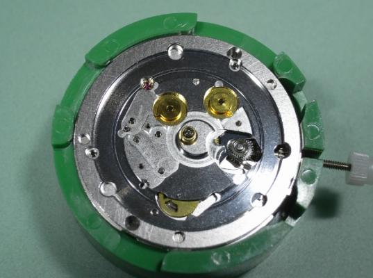
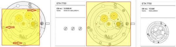
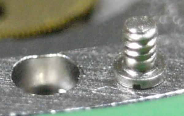
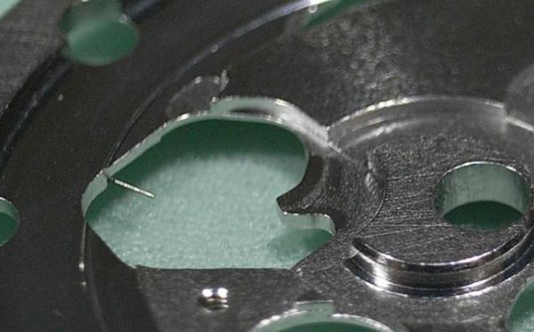
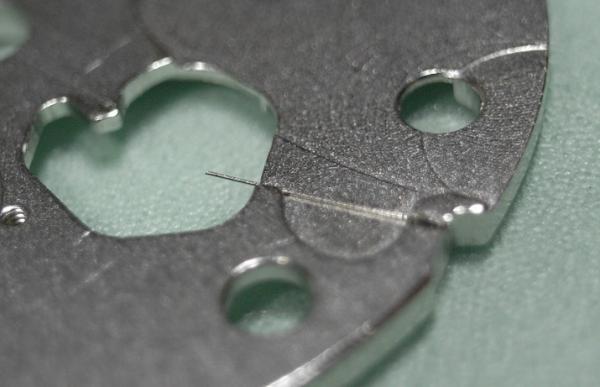
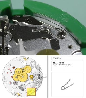
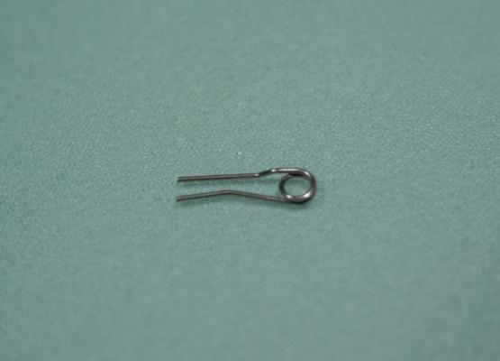
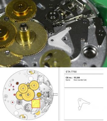
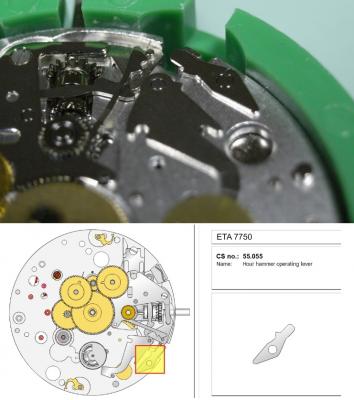
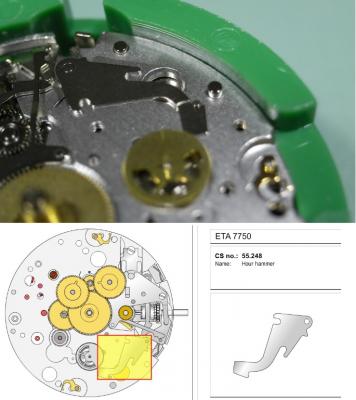
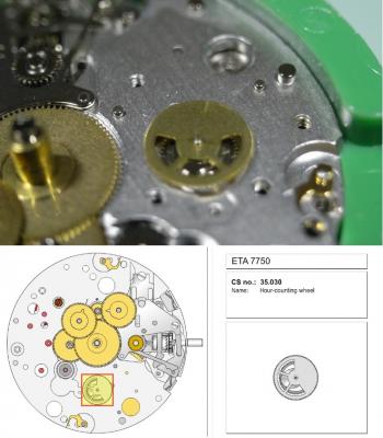
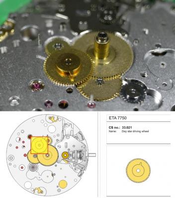
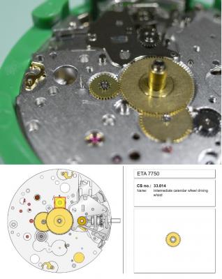
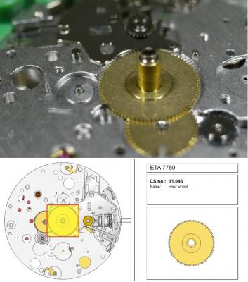
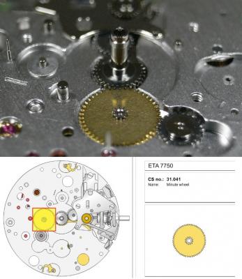
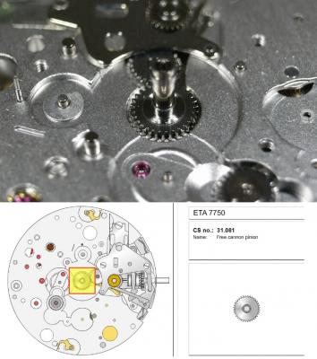
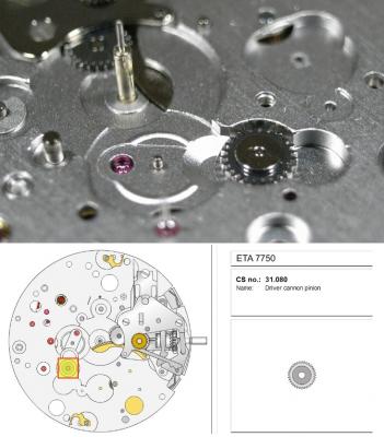
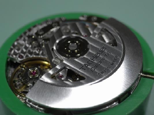
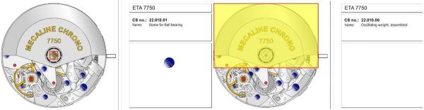
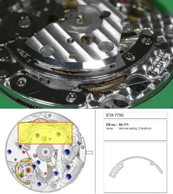
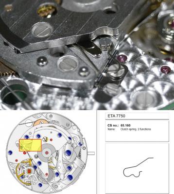
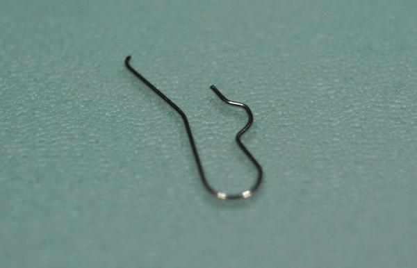
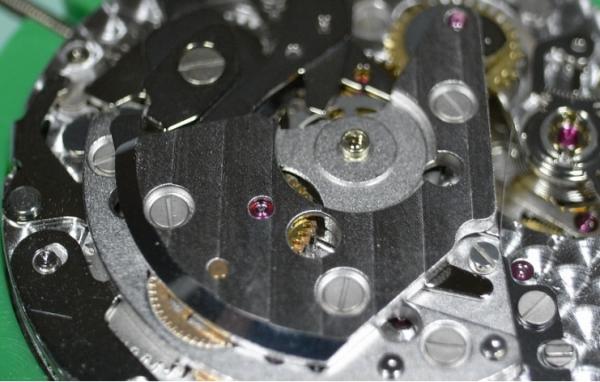
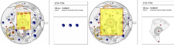
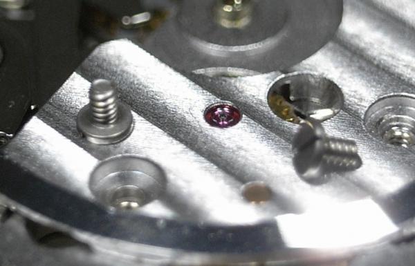
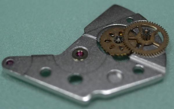
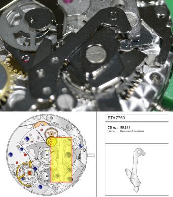
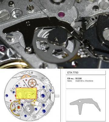
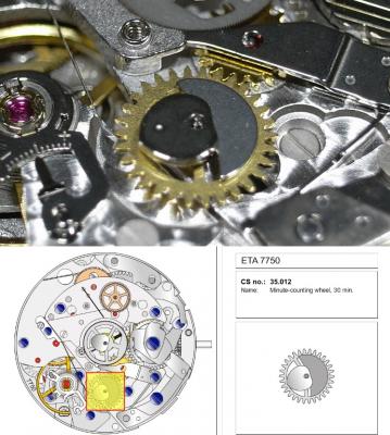
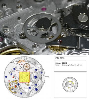
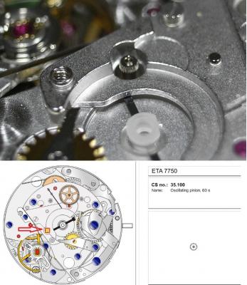
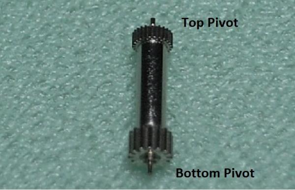
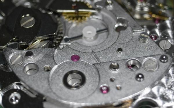
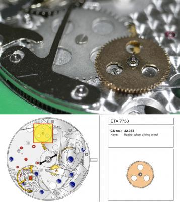
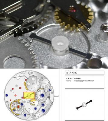
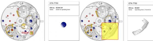
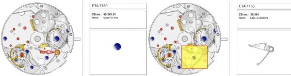
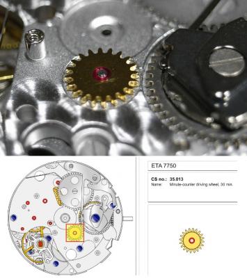
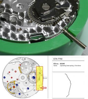
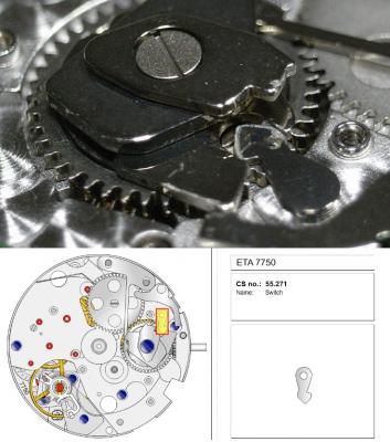
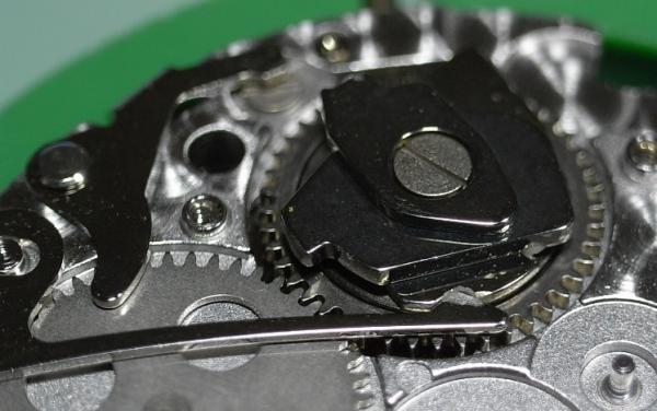
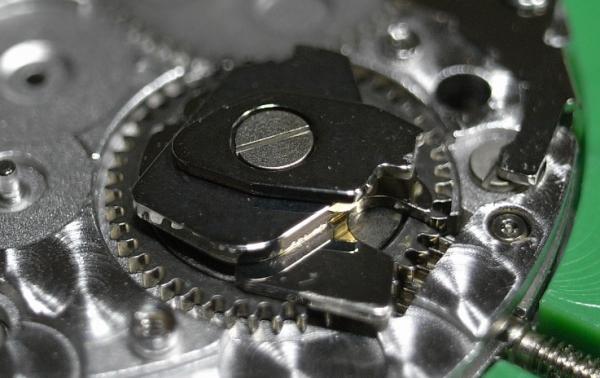
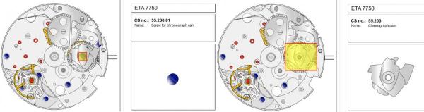
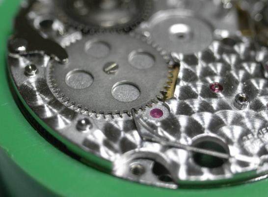
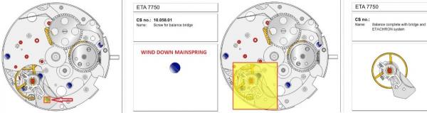
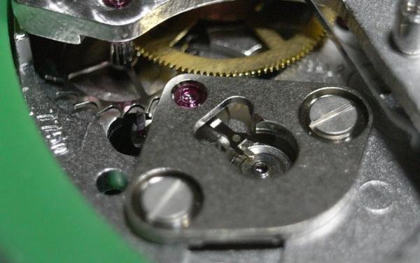
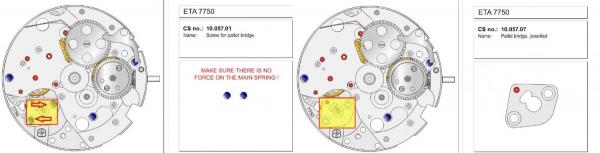
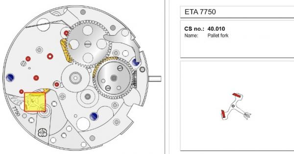
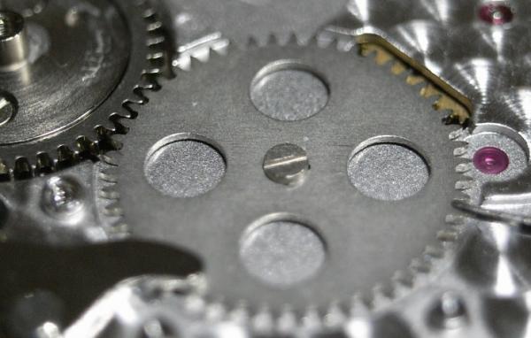
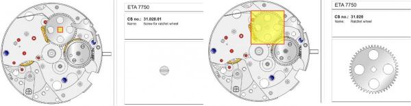
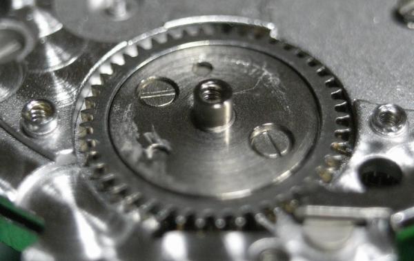
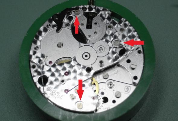
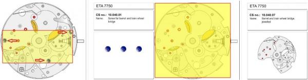
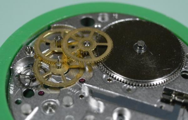
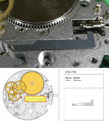
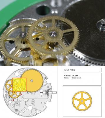
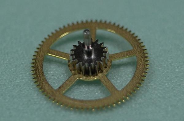
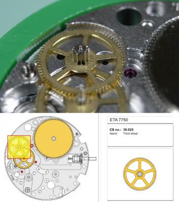
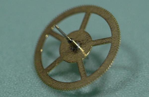
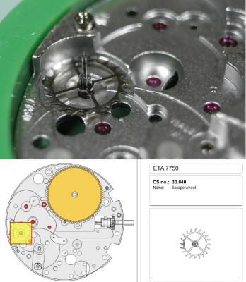
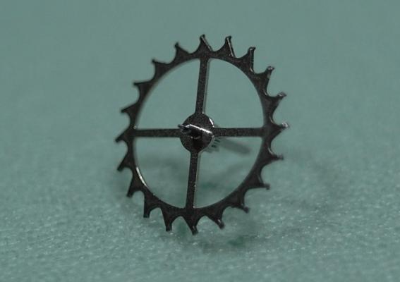
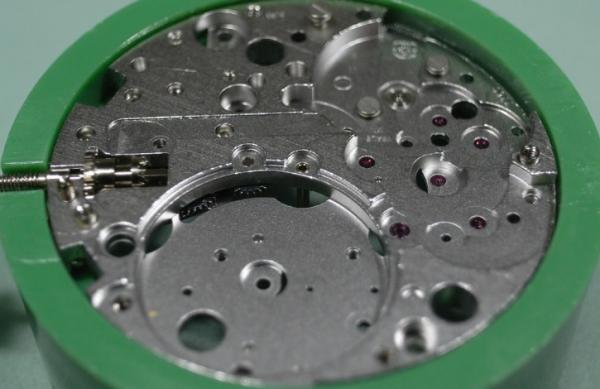
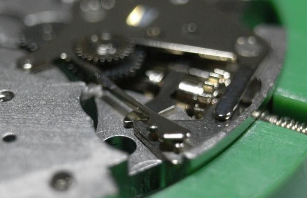
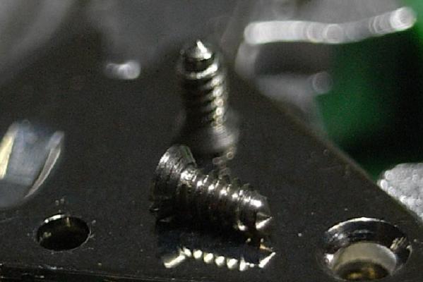
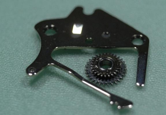
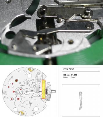
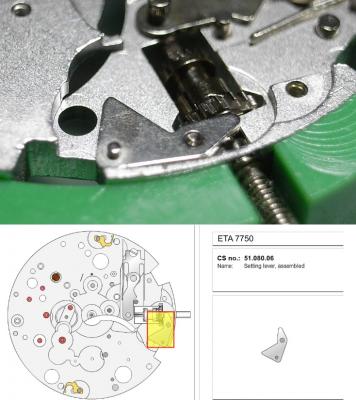
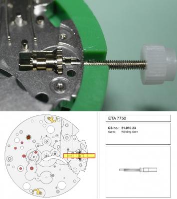
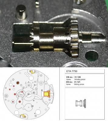
ETA 7750 Service Walkthrough The 7750 was first available in 1974, having been one of the first movements to be designed with the aid of a computer. It's hard to believe that the 7750 is still the industry standard movement for chronographs considering it's history. It was developed over 40 years ago by Valjoux, who was then a legendary movement maker that was part of the giant ASUAG conglomerate. But by the end of 1975 production was stopped due to the onslaught of the Quartz Era, and the 7750, along with many other mechanical calibers, was abandoned. Industry demand for this movement was so low that the stock produced in that 1 year manufacturing lasted until 1982! Such was the devastation of cheap Japanese produced quartz watches to Swiss manufactures. History may have forgotten the 7750 except for the local management at Zenith who ignored the orders by Valjoux to destroy the dies and equipment used to manufacture the 7750, instead hiding the equipment away from corporate eyes. You can find many more fascinating facts about this caliber online, and it's well worth the read. ................................................... This walkthrough will be very detailed, and I hope this will give people the courage to tackle this movement. I've serviced quite a few calibers, and this is one of the most beautiful, with a very logical layout. ETA7750 Tech.PDF If you have built your skills with basic movements, and become proficient in servicing them, I would highly recommend this movement to be your first chronograph to tackle. Lets begin. DEMAGNETIZE THE MOVEMENT BEFORE DISASSEMBLY. Remove the Day Indicator and store it in a safe place where it won't be damaged. Unscrew (0.8 Driver) the Jumper Maintaining Plate and remove it. Do the same for the Date Indicator Maintaining Plate Carefully remove the Jumpers Spring, holding it with a piece of pegwood so it doesn't ping away. Next remove the jumpers for the day and date. The jumpers differ from one another, so here is a reference photo so you can see the difference. Remove the Date Indicator and place it in a safe place where it won't be damaged. The last piece to remove on the Date Platform is the Double Corrector Now unscrew (1.4 Driver) the Date Platform and gentle pry it from the movement. Be careful when removing this plate, as there is a fine spring pressed into the plate that can be easily damaged. Here is a reference photo of the screws that hold the Date Platform. Remove the Hour Hammer Spring, once again using the pegwood to hold the spring while removing the tension. Here is a reference photo of the correct orientation of the spring. Remove the Hour Counter Lock. Remove the Hour Hammer Operating Lever. Next is the Hour Hammer, be careful when removing this item so as not to damage the Hour-Counting Wheel. Now remove the Hour-Counting Wheel. Remove the Date Indicator Driving Wheel Remove the Day Star Driving Wheel Then remove the Intermediate Calendar Driving Wheel Remove the Hour Wheel Then the Minute Wheel Remove the Cannon Pinion, which does not require a puller. The last component to be removed on this side of the Main Plate is the Driver Cannon Pinion. To lift the Driver Cannon Pinion I used what Mark used, a set of hand lifter from Horotec (MSA05.007); but you can also use a Presto Tool (30636-1) which will also work well. The dial side of the movement is now complete disassembled. Flip the movement over and unscrew (1.5 Driver) the Oscillating Weight. To remove the Hammer Spring lift it up gently over the automatic work and move it inwards. This will move the tail of the spring in a clockwise motion to the opening in the slots, which will free the spring. Slide out the Clutch Spring. Here is a reference photo of this spring, and it's orientation. Remove the screws (1.4 Driver) for the Automatic Device Bridge, and gently pry it loose. Here is a reference photo of these screws for the bridge. Once the Automatic Bridge has been removed, the two wheels for the automatic work are able to be removed. Below is a reference photo of how the sit inside the bridge. We now begin to disassemble the chronograph section of this movement. Begin with removing the Hammer, 2 Functions. Next remove the Clutch 60s, 2 Functions. Then remove the Minute-counting Wheel, 30min. Remove the Chronograph Wheel 60s, 30min. Gently lift out the Oscillating Pinion, 60s. Here is a reference photo of the orientation of this pinion. Unscrew (1.4 Driver) the Chronograph Bridge and gently pry it off the Train Wheel Bridge. Remove the Ratchet Driving Wheel. Remove the Chronograph Wheel Fiction. Unscrew (1.4 Driver) the Operating Lever, 2 Functions. Unscrew (1.4 Driver) the Lock, 2 Functions. Next remove the Minute-counter Driving Wheel, 30min. Slide out the Operating Lever Spring, 2 Functions. This spring can be fitting in both directions; but only 1 way is correct. Here is a reference photo of it's correct orientation. Remove the Switch. Here I digress from the order the SwissLab document illustrates the order of removal. They show to remove the Chronograph Cam before removing the Hammer Cam Jumper. This in my opinion is not the best way, as all the force from the jumper is pressing on the cam whilst your trying to remove it, and could lead to damage. Instead I move the Chronograph Cam until it reaches the notch as shown in the photo below. Then lift the Hammer Cam Jumper up to the top of the Chronograph Cam, which will release it's tension. Then, just as you removed the previous hammer, rotate the jumper to the opening in the slots, which will free the spring. Now you can unscrew (1.4 Driver) and remove the Chronograph Cam safely without tension on it. RELEASE THE MAINSPRING TENSION Once the tension has been released, unscrew (1.4 Driver) and remove the Balance Cock. Then unscrew (1.4 Driver) the Pallet Bridge and remove the bridge and Pallets. Unscrew (1.2 Driver) and remove the Ratchet Wheel. Then remove the Crown Wheel. Unscrew (1.4 Driver) the Train Wheel Bridge and gently pry it off the Main Plate. Note that one of the screws is under the Operating Lever. This needs to be moved out of the way to access this screw. The last level of this movement contains the train. Here is a reference photo of the wheel locations. Remove the Stop Lever. Remove the Great Wheel. Here is a reference photo of the underneath of this wheel. Remove the Third Wheel. Here is a reference photo of the underneath of this wheel. Remove the Second Wheel. Here is a reference photo of the underneath of this wheel. Note this has the long lower pivot. Remove the Escape Wheel. Here is a reference photo of the underneath of this wheel. Then remove the Barrel. This completes the removal of the train. Flip the movement over so we can complete the disassembly by removing the keyless work. Firstly, release the tension from the Setting Lever Jumper. Then unscrew (1.2 Driver) and remove the Setting Lever Jumper. These are unique screws with pointed ends, and below is a reference photo of them. This will also remove the Intermediate Setting Wheel. Next remove the Setting Wheel Then remove the Yoke. Remove the Setting Lever. Remove the Rocking Bar. Now pull out the Stem. Once the Stem is removed the Winding and Sliding Pinion should fall out of the movement onto your work mat. Disassembly of the 7750 is now complete If you've come this far, congratulation on completing the disassembly. Make sure you pegwood all the jewels and reinstall the Balance back onto the movement for cleaning. Assembly of the movement will be posted as soon as I complete the write-up.


 3 points
 -
Thanks mate :) But all praise goes to my Lord and Saviour, Jesus Christ, for giving me the gift of being able to do this work and write-ups for you guys. My hope is that they inspire others to "give it a go" like I did 11 months ago, and not be fearful of a challenge. The reward that comes from succeeding and seeing a movement come to life are hard to put into words.1 point
-
Get yourself a large steel or brass washer, big enough for the hole to be slightly smaller than the inside diameter of the mainspring barrel. Wind the mainspring into your winder, left handed or right handed, it doesn't matter. Install the mainspring into the hole in the washer. Transfer mainspring from washer to barrel as you would a new mainspring. Save yourself a fortune by equipping yourself with a good selection of large washers.1 point
-
It has been mentioned before in the forum. You are better to use a lathe collet or a pin vice to reduce the diameter. Just remember that a wee squeeze can go a long way.1 point
-
Dear Geo, Thank you for your kind words. It is impressive how helpful and just plain nice everyone here is. Horologically I am a true amateur. I work on my own watches and occasionally put together a unique watch as a gift or thank-you. I owe any knowledge I have to this forum and Youtube videos. I do have some experience with precision small parts manufacturing/prototyping from prior ventures and I hope that can be useful to share with the users of this forum. Again, thank you all for sharing your craft. It is truly appreciated.1 point