Leaderboard


Popular Content
Showing content with the highest reputation on 01/25/15 in all areas
-
When fitting new stems to watches I use these tools :- Digital calipers, Fine grade diamond lap Wire cutter Pin vice Now for fitting. (1) Hold the stem in the pin vice and screw on the crown tightly by hand. (2) With the movement fitted correctly in the case, insert the stem until it locks in place. Now measure the gap between the case and the underside of the stem. In this case it is 2.16mm. (3) Subtract 0.2mm from this size and this will give the amount to remove from the stem. In this case it will be 1.96mm which will give 0.2mm clearance below the crown when fitted to the watch. (4) Now remove the crown from the stem and hold the stem very tightly in the pin vice, then place the pin vice and stem between the jaws of the digital calipers then zero the calipers. (5) Remove the calipers and without touching the zero button set them to minus 1.96mm. THEN RE-ZERO THE CALIPERS AT THIS LENGTH The wire cutters are now used cut off the excess thread leaving a small amount to be filed to the exact length. (6) All that is required now is to dress the stem with the diamond lap a little at a time until the calipers read zero. (7) Finally screw the crown on tightly and it should be ready to fit to the watch without further adjustment. I find that this method cuts down on trial and error. FOR SCREW DOWN CROWNS. A) Screw down the crown tightly onto the case without the stem and measure the distance nbetween the bottom of the crown and the case. B ) Screw the new stem tightly into the crown, then insert into the watch until it engages and locks into the movement. C) Press the crown down firmly as far as it will go and hold it there. D) Using the vernier callipers, measure the distance between the bottom of the crown and the case. E) Subtract the size determined in (D) from the size measured in (A) then subtract a further 0.15mm from this size. This is the amount to shorten the stem by. This should allow the crown to screw full home without compressing the stem too tightly between the movement and the inside of the crown. F) Cut the stem leaving it slightly longer than the size determined in (E), and dress down to size using the diamond lap and vernier callipers as described in the original post. G) Screw the crown onto the shortened stem and check fit and function, before using a tiny spot of Loctite 221 to secure. Click here to view the article1 point
-
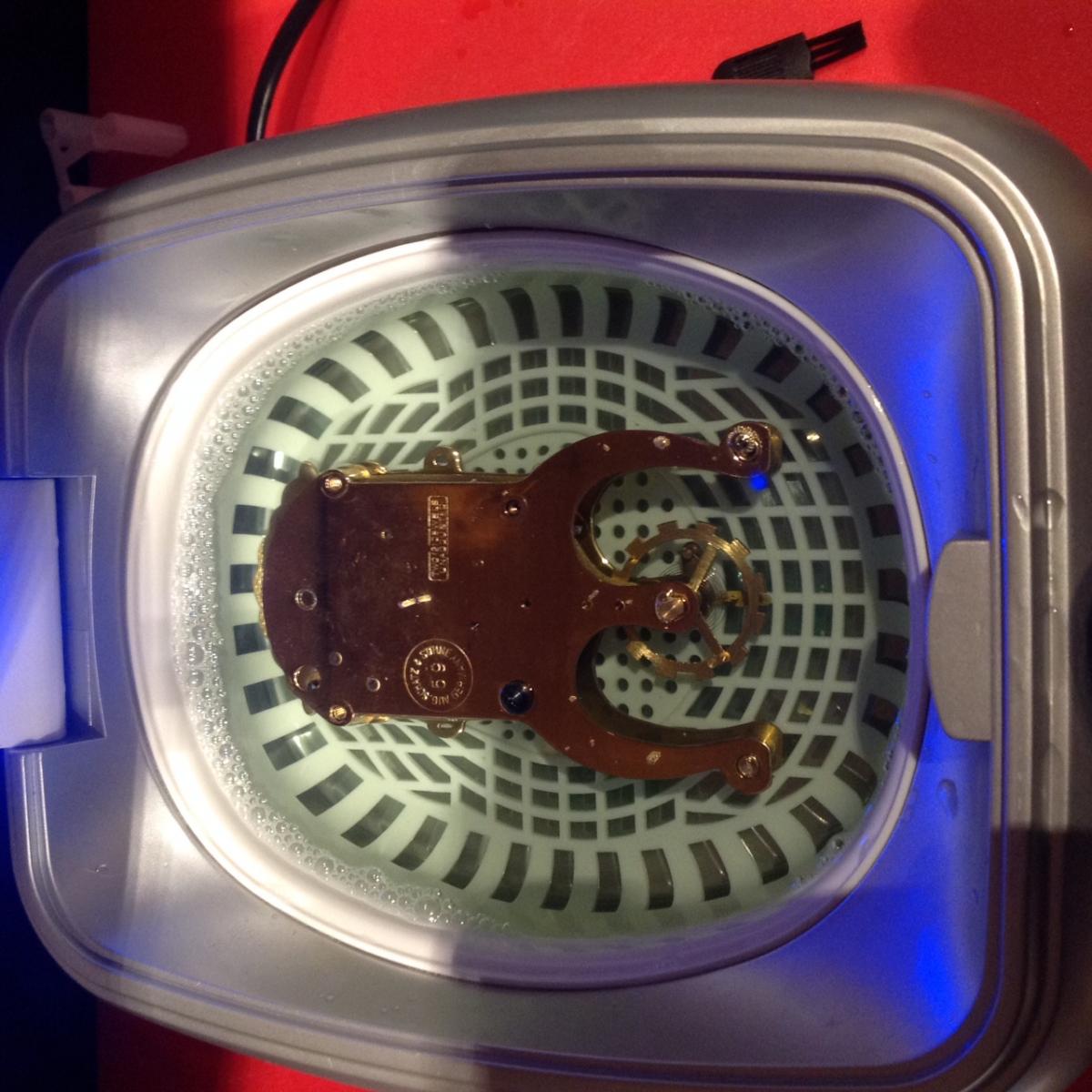
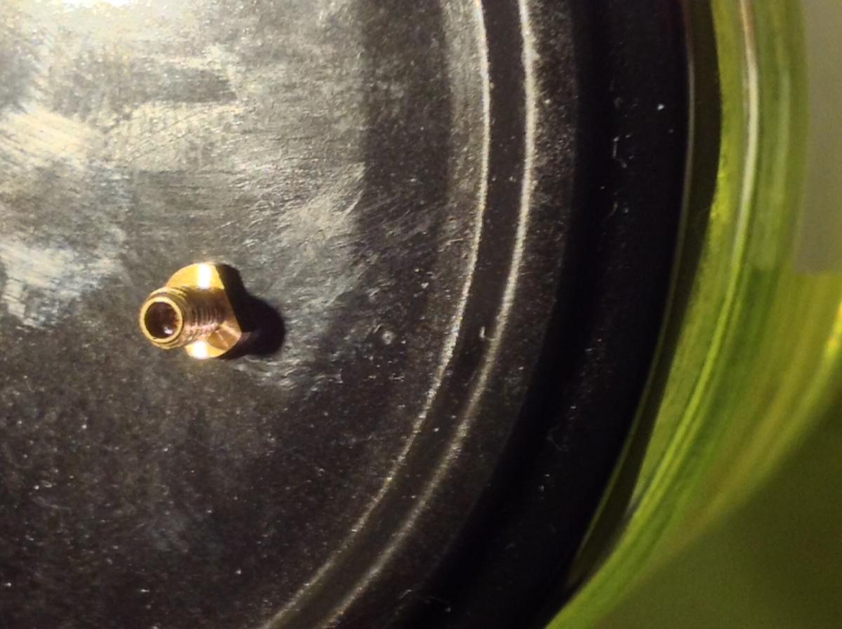
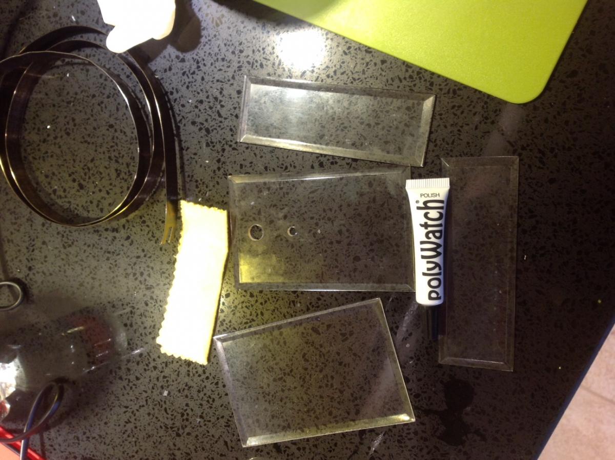
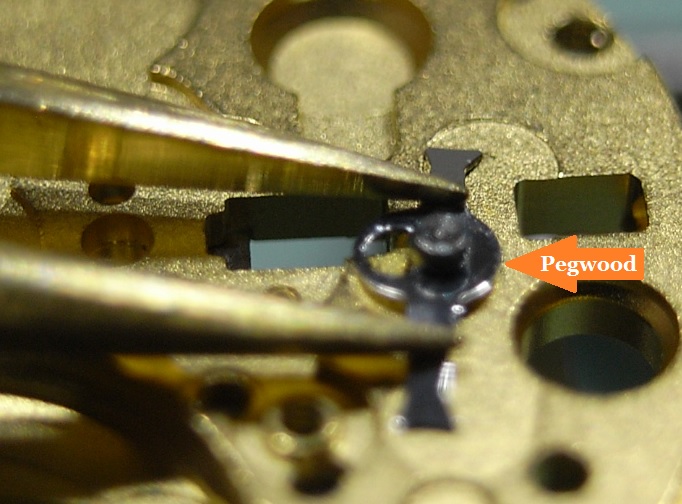
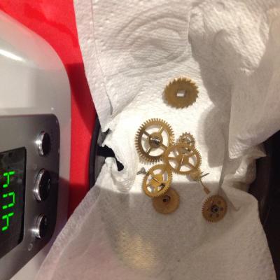
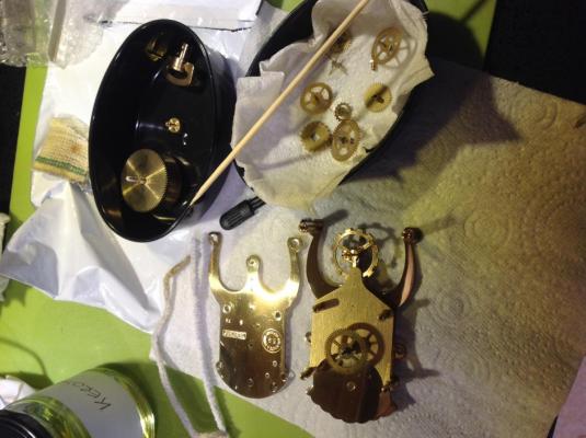
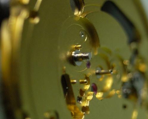
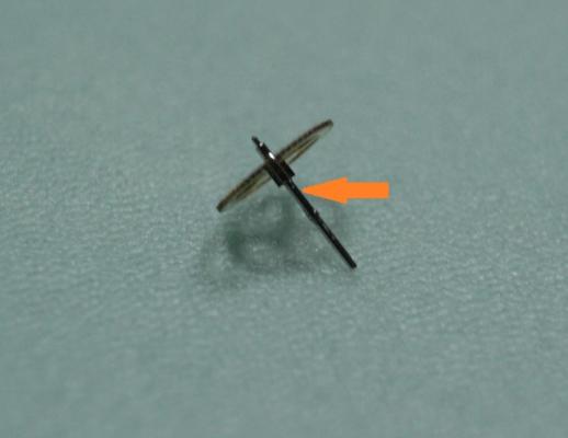
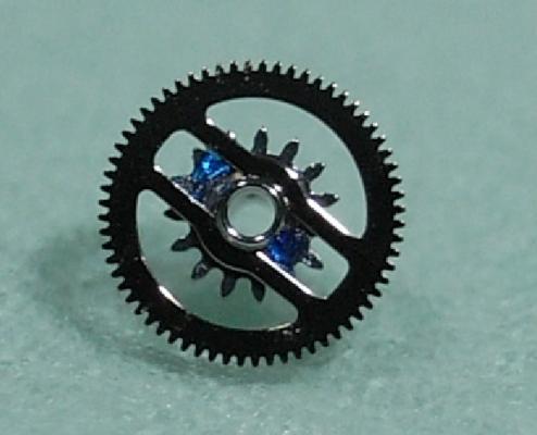
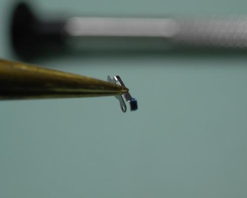
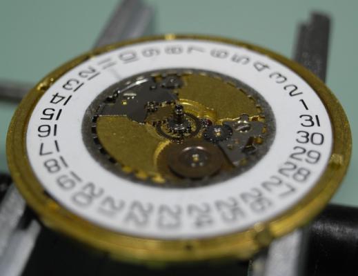
Well the prep is just about finished, I put the spring back in between the plates to clean like I would have if it was a watch. Also cleaned all the other pieces Drying time and pegwood on the pivot holes just to make certain. This is the screw with a jewel inside (one of two) that go to each end of what I would call a balance staff on a watch. Holds the staff, wheel and spring in place. Ok thats about all I have polywatched the acrylic lightly (pic is before) then gave it a short burst in the ultrasonic cleaner and it has come up a treat. There are a few marks on it but I don't think I will try for absolute perfection, it is all clean and shiny and the marks left are only indicative of the age. Right I am off upstairs to try to put it together. Cheers, Vic


 1 point
 -
Most of my measurements are done with a set of digital callipers, but when it comes pivots and jewels I use a Feintaster. This I'd a specialised dial gauge measuring device made specifically for horological work. Check out this thread:- http://www.watchrepairtalk.com/topic/657-any-advice-on-a-nice-accurate-vernier-gauge/?hl=feintaster#entry48001 point
-
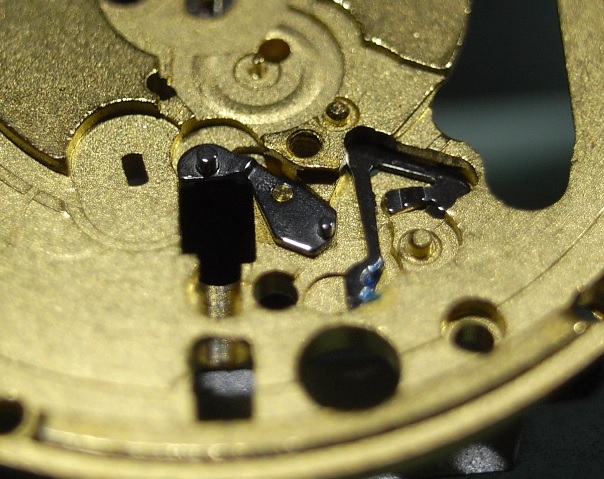
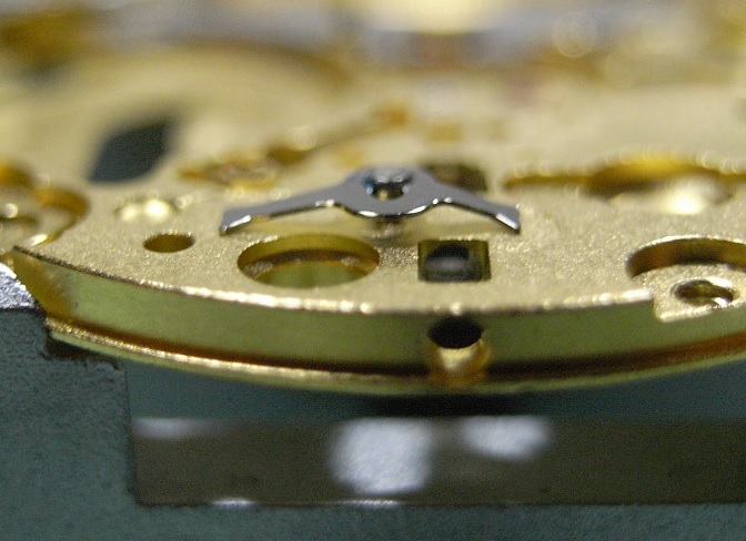
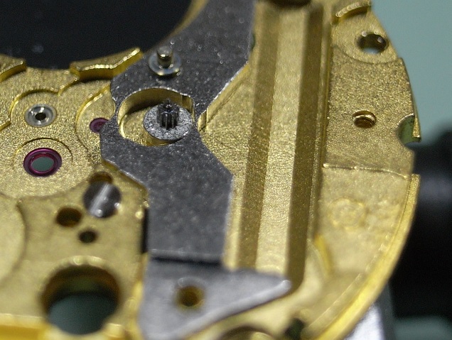
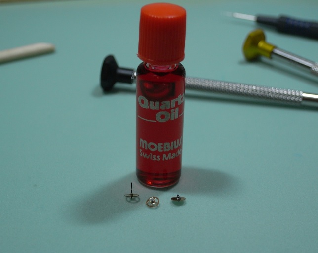
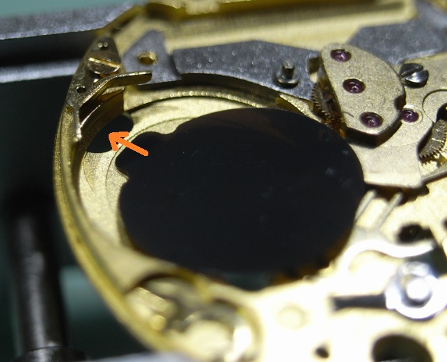
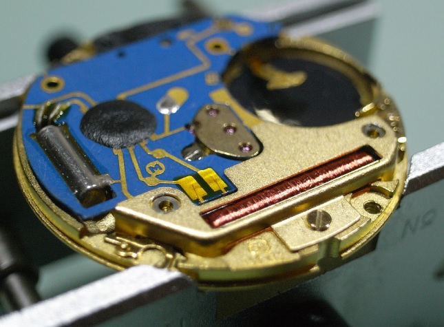
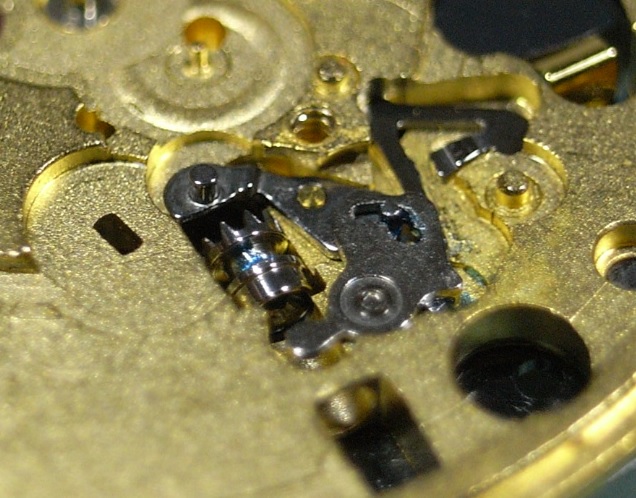
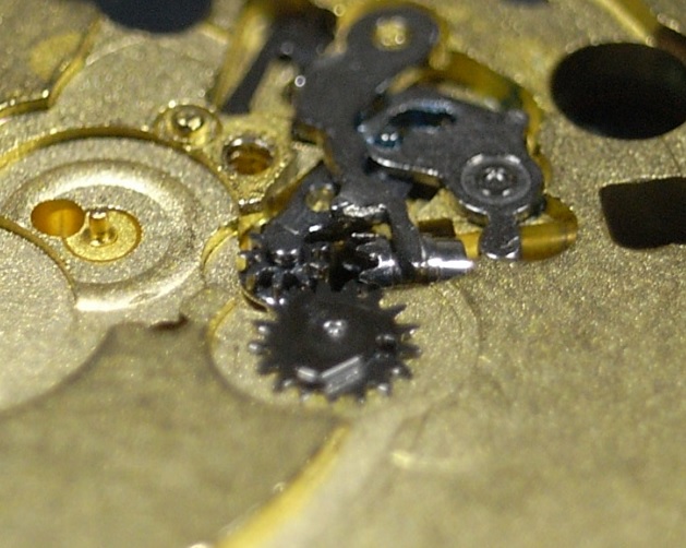
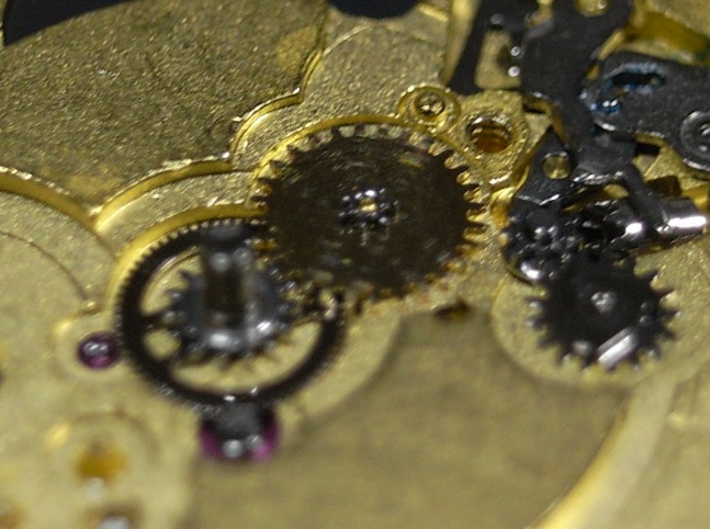
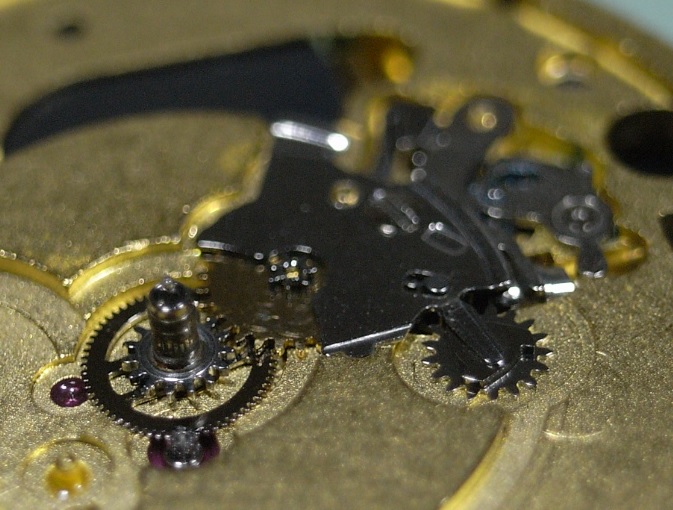
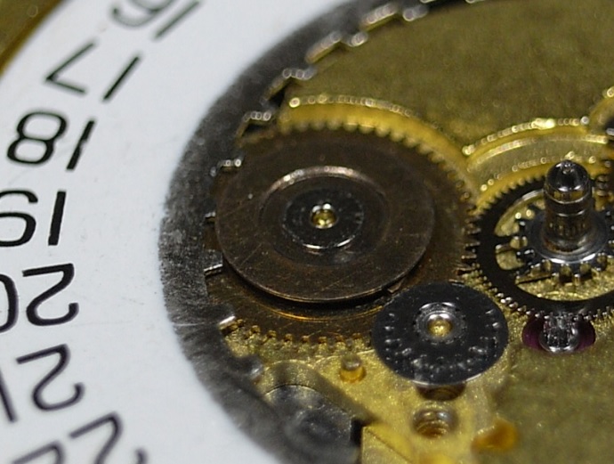
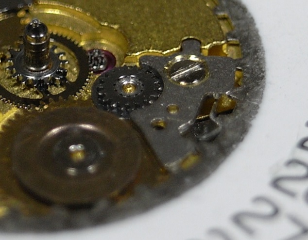
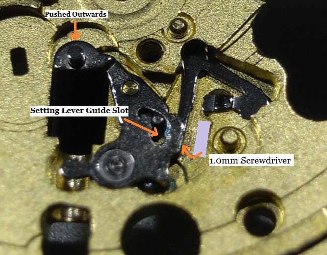
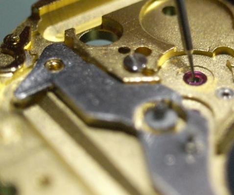
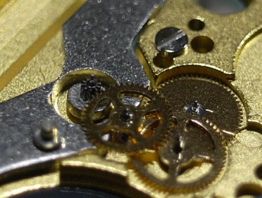
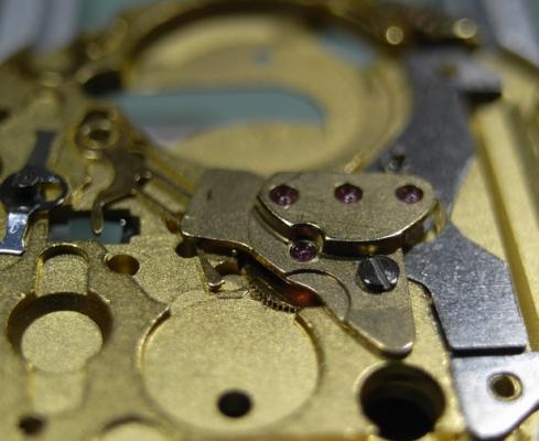
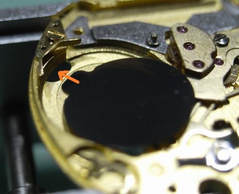
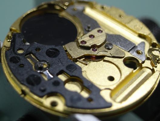
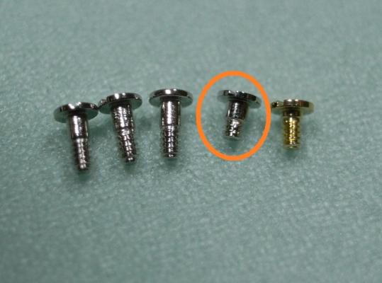
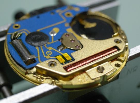
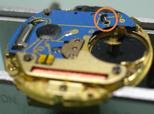
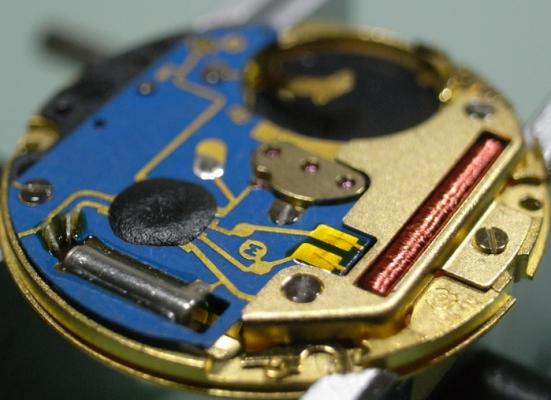
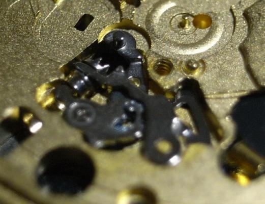
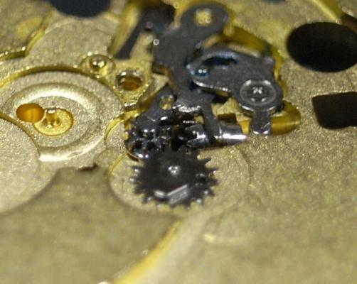
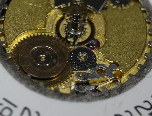
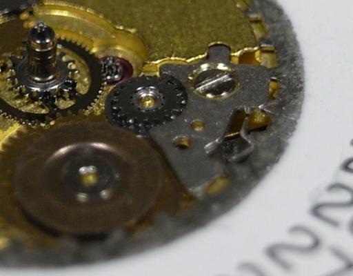
Assembly I have made the assembly walkthrough much more detailed, as putting things back together is always more tricky than pulling them apart :) Firstly install the Setting Lever Jumper and the Double Corrector Operating Lever. D5 on the Corrector Lever Pivot 9501 on the Setting Jumper To install the Setting Lever, first move the Double Corrector Operating Lever to it's most outward position, then push the Setting Lever 1/3 of the way down it's pivot, next place a 1.00mm screwdriver as shown below, and turn it clockwise. This will push the Setting Lever Jumper over to the other side of the pin on the underneath of the Setting Lever. Then push the Setting Lever home, making sure that the pin on the Double Corrector Operating Lever locates inside it's guide slot on the Setting Lever. I know this sounds a little complicated; but once you study the Keyless Work, you will understand the procedure I've explained here. Just take your time, and read through this procedure whilst looking at your work a couple of times until you are sure you've got it. Please Note: If you use a larger size of screwdriver be careful you don't push it too far over and bend the jumper ... using a 1.00mm driver is the correct size and will avoid this possibility. 9501 on the Setting Lever pivot 9501 in the guide for the Corrector Lever pin Flip the movement over and place the Setting Lever Spring Clip as shown below Then with a pair of tweezers push down on both sides of the clip and with a piece of Pegwood push it inwards so it locks in. Next install the Rotor, and you'll find due to it being magnetized, it will stick to the Stator. DO NOT try and locate it in it's jewel, as it will just pop out and stick to the Stator again, and this can be very frustrating ... but I have a little trick that will cure this :) Place one of the screws on the opposite side of the Main Plate, behind where the Rotor is located, and you'll see it will be attracted to the Rotor (as seen below). This little screw will pull the Rotor downwards and stop it being pulled over by the Stator, so you now can locate it in it's jewel. Don't forget to remove and demagnetize the screw once you've completed installing the gear train. There is a LOT of discussion on oiling quartz gear trains. The ETA Service Manual says to use Moebius 9014 on this particular movement; but I prefer Moebius Quartz Oil, as it can be used on both metal and plastic gears without concern ... why have 2 oils when 1 will suffice for both applications. Others say, don't oil the gear train at all, as it just adds load to the movement and makes it draw more current. Personally, I'd rather change a battery a little earlier than change out a worn out movement ... you choose which is cheaper. When oiling any quartz gear train, we only apply about half of what you'd use on a mechanical movement ... it's called Ghost Oiling. That being said, ghost oil the jewel for the Third Wheel with Quartz Oil as shown below. Ghost Oil the upper part of the Second Wheel with Quartz Oil as shown below Fit the Gear Train into the Main Plate. Place the Gear Train Bridge over the wheels, locate the pivots carefully until all are freely spinning, and tighten down the bridge. Remember once the screw makes contact with the bridge, STOP, and recheck the free spinning of the train before completely tightening the screw. Once the Bridge is secure, place the Stop Lever and Switch back onto it's pivot. D5 for Stop Lever and Switch pivot Quartz Oil for all Gear Train pivots (remember to oil both sides) Next install the Battery Isolator, making sure to push the tab into it's slot as shown below. Then install the Isolator Block Next we need to short out the screws for the IC Board. You'll see there is a Gold Screw, this is for the Coil Protector, and then there are three screws of the same length, and one shorter one. The shorter screw must be place into it's correct hole. Locate the IC Board onto the movement. Before I screw the IC Board down, I always fit the Coil Protector first. This helps avoid any damage if you accidently slip off a screw head. Remember to use the Gold Screw. Next place all the rest of the screws into their holes, noting the position where the short screw is to be located. This side of the movement is now complete. Time to flip it over and complete the Keyless Work, Motion Work and Calendar Work. Place the Sliding Pinion into it's position. Please Note this is a spare movement I'm using here, and I don't have a stem. If you have a stem, now is the time to install it. 9501 in the grove for the yoke on the Sliding Pinion 9501 on the stem Place the Yoke into position D5 on Yoke Pivot Install the Setting Wheel and Date Corrector D5 on Setting Wheel pivot D5 on Date Corrector slot Next is lubricating the Cannon Pinion. This is one step that MUST be done correctly, otherwise too much friction will occur and you'll damage the Setting Wheel in short order. 9501 Canon Pinion fiction points Place the Canon Pinion and then the Minute Wheel D5 Minute Wheel pivot D5 Ghost Oil the Canon Pinion Tube Attach the Motion Work Bridge and secure it down. Place the Date Ring onto the movement, and then slide the Date Indicator Driving Wheel into place, so the teeth of the Date Wheel are inside the Driving Wheel. Then install the Intermediate Date Wheel. D5 Date Indicator Driving Wheel pivot D5 Intermediate Date Wheel pivot Lubricate the foot of the Date Jumper Spring as shown below 9501 Date Jumper Spring foot Place the Date Jumper Spring into position on the movement Place the Date Jumper Maintaining Plate and secure it. Check the date and time setting, making sure the quick date works smoothly. Check the feel of the Motion Work, making sure there is not too much or too little friction from the Canon Pinion. Your movement is now completely serviced, all that's left to do is fit Hour Wheel, Dial and Hands :woohoo-jumping-smiley-emoticon: It's good for another 100,000 miles or 5 years ... whichever comes first ^_^ I hope this walkthrough both helps and encourages you with servicing your 955/6 ETA Movement


 1 point
 -
That is a pure Aussie invention with an appropriate name ... all our very best inventions have "**BLEEP**" in their product name :p That stuff is good for everything: from a lawn mower that won't start up, to a hang-over cure, and breath freshener for the morning after :wub: ... Honestly! I wouldn't lie about such things! :rolleyes:1 point
-
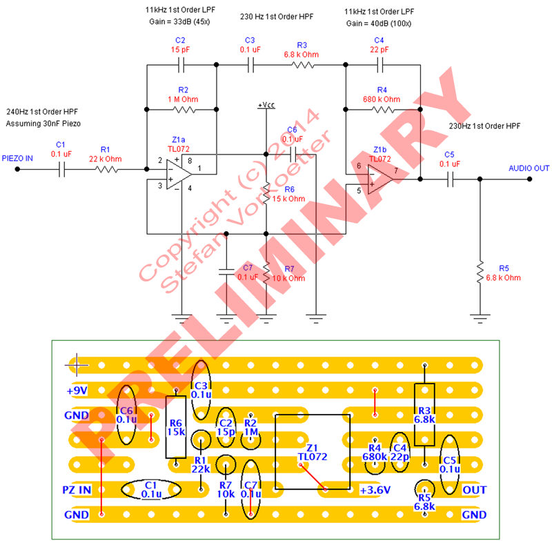
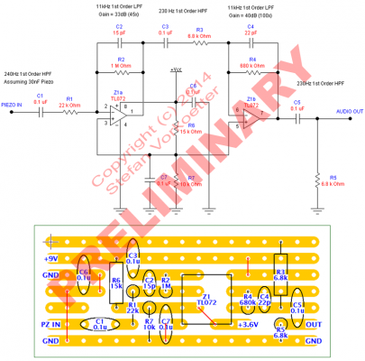
I'm finishing up the first version of the software now, and will be sending it and a prototype mic/amp to a watchmaker friend. I still haven't decided on a distribution scheme. Most likely free and pro versions of the software, and the pro version can also be purchased bundled with a mic and amp. For those who urgently want to build their own now, the mic element is a 27mm piezo disk, readily available on eBay. Power is provided by a 9V battery, which is good for about 50+ hours of continuous use. Here's the current version of the circuit I'm using, along with a stripboard layout. Please don't redistribute it on other forums and such for now. This amplifier will work with Biburo too, but I've found Biburo to be pretty bug-ridden and unreliable, which is one reason I decided to write my own software.
 1 point
 -
What I find interesting about this link is what is included over what is not included! They have listed the school that I'm attending in the fall (a small non-certified, non profit night study program called Norwest School of Horology that will cost me about $1200) over a program that is located in the same city that is recognized as a formal degreed program AND sponsored by Rolex and the Swiss American Watchmakers Training Alliance (SAWTA), The Watch Technology Institute @ North Seattle Community College($14,000). Not sure if they didn't know about this formal program but I bet it has really "Ticked" off(pun intended) Rolex!1 point