Leaderboard


Popular Content
Showing content with the highest reputation on 03/16/17 in Posts
-
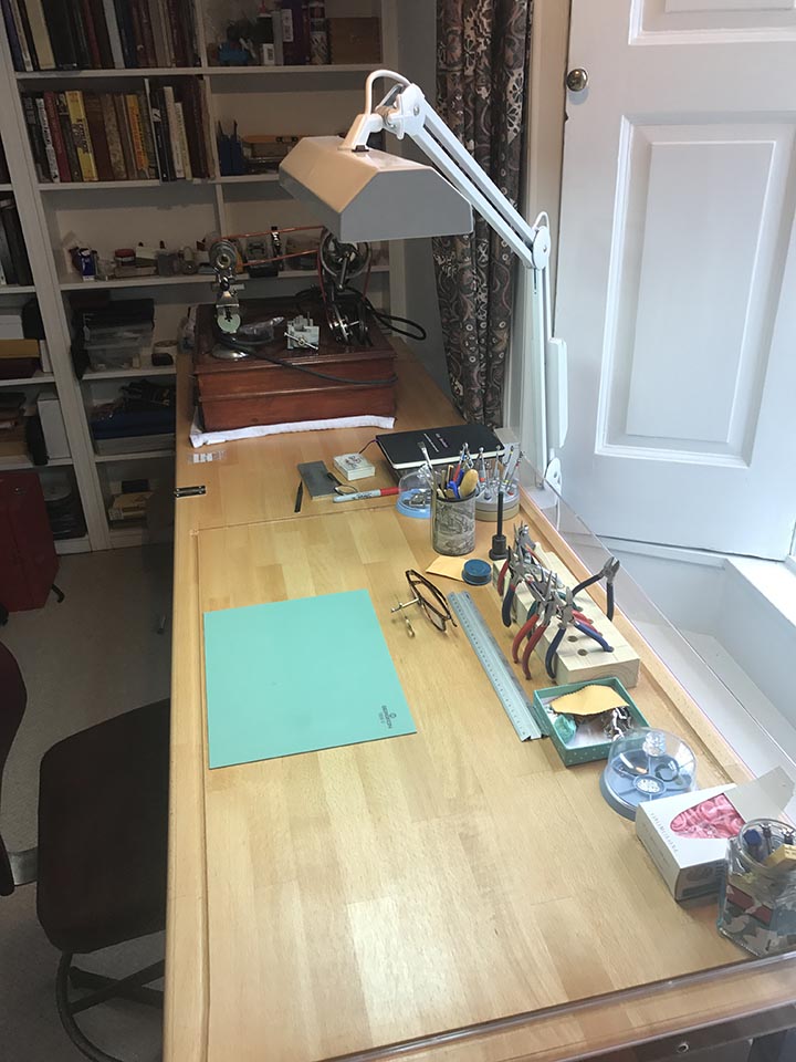
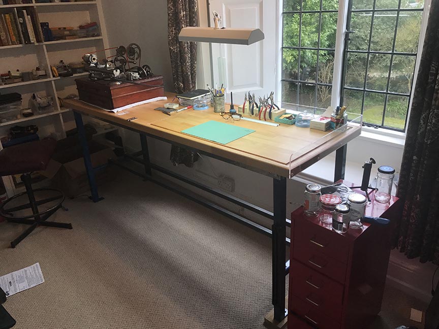
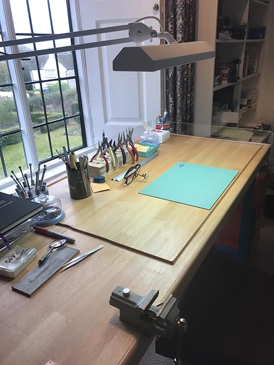
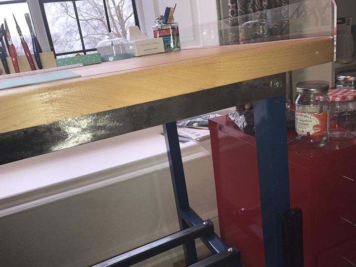
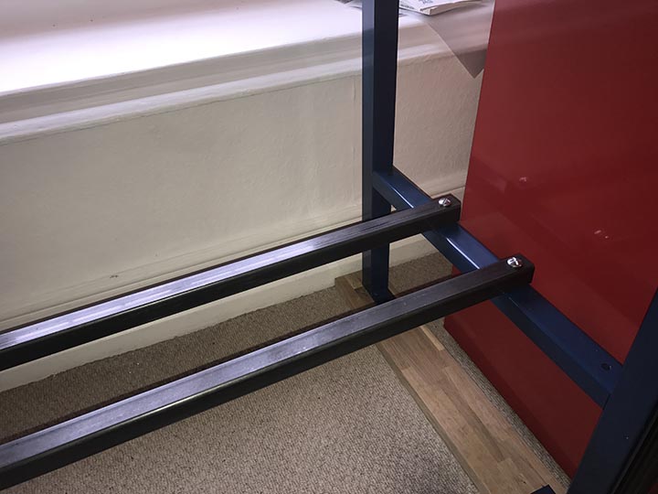
Like a proud father, I feel the urge to show off my latest creation. We recently moved to a new house which finally gave me the space to have an office/workshop. I have been working on a tiny little homemade bench the past few years and have been dreaming of a proper bench. Sadly the ready made ones I wanted are way out of my league. My design goals were: Affordable versatile Free standing (i rent the house and cant drill bolts into the walls) Sturdy I got the original inspiration from Dan Spitz. http://danspitz.com/for-sale/ His concept is to make stunning workbench tops. You then supply the legs. However at £2,000 for the top, there was that budget thing again. I did however steal his idea (I don't actually know if he or someone else came up with it) of the routed groove along the edge. It has already proved to be a godsend in terms of catching small screws, and the odd tool. I decided to add a perspex screen on the back and down one side as I am notoriously rubbish at not flicking click springs etc across the room. So, the basics. Worktop: 40mm solid Beech kitchen work surface from Ebay 2000mm x 620mm - £85 Legs: Steel workbench legs from Machine Mart about £40 including shipping Bench support: 2 L shaped steel struts from an old Victorian bed. £5.00 from a salvage yard, cleaned up with an angle grinder then polished. Struts: 30mm square steel tubing from steel merchant £20.00 Danish oil for bare wood: £5.00 (four coats on either side) £20 for bolts and screws. So I made the whole thing for well under £200. The top is extremely heavy and I haven't totally managed to eradicate minimal side movement and ideally I would bolt it to the wall but as I said I can't. Still it isn't going anywhere and I love it. Of course you don't have to make it 2m long but I wanted somewhere for my lathe. I am building a perspex divider to protect the workbench from cuttings from the lathe. Anyway, I hope it might give some of you some ideas.

 2 points
 -
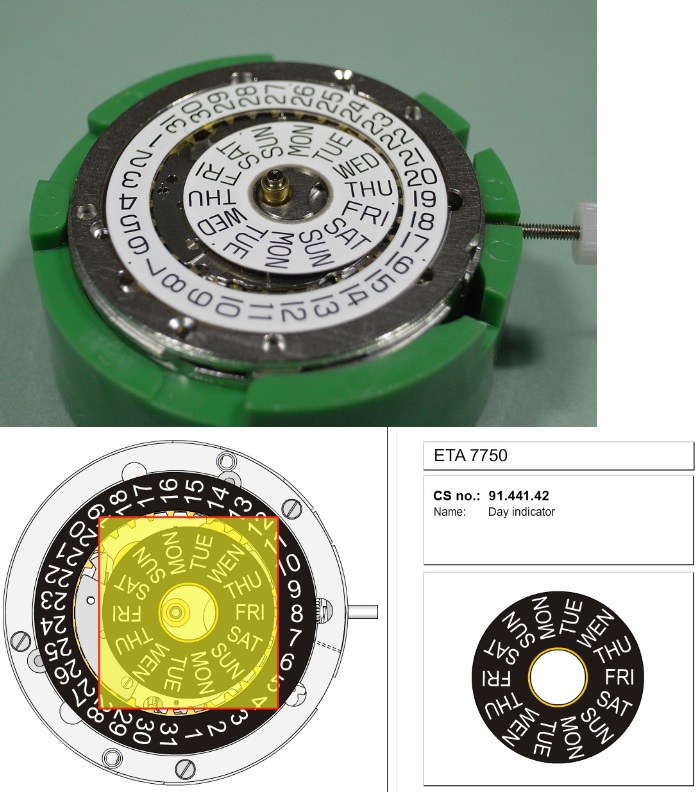
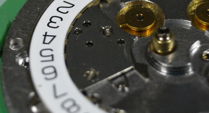
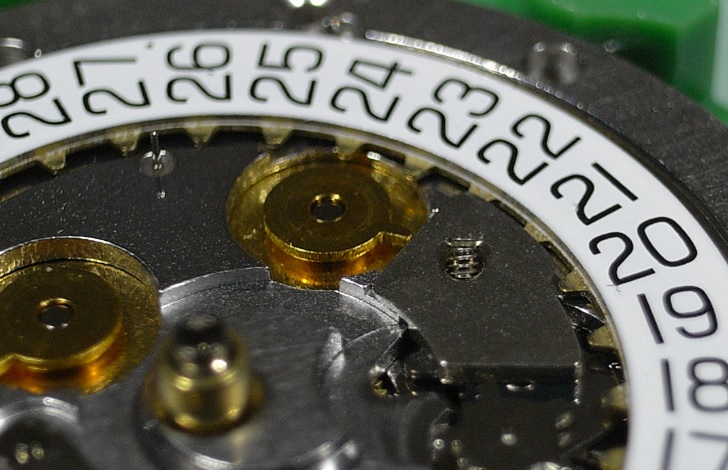
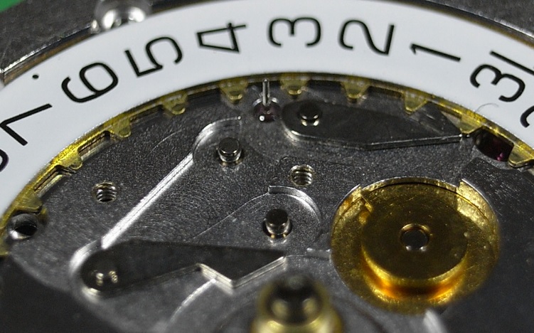
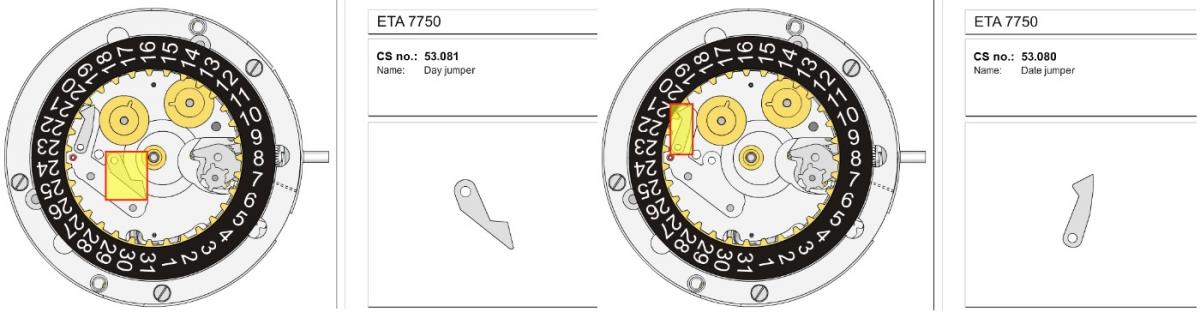
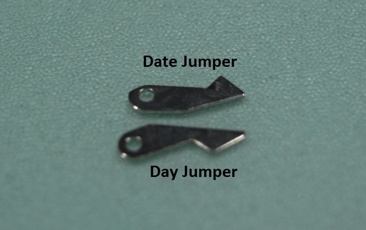
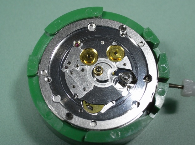
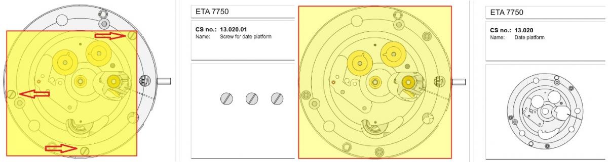
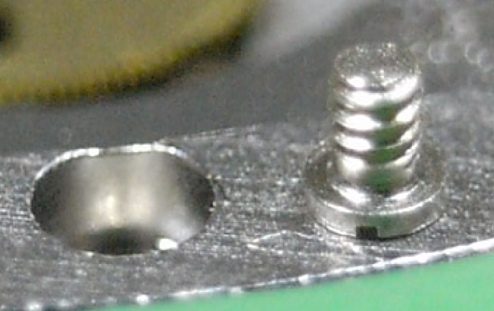
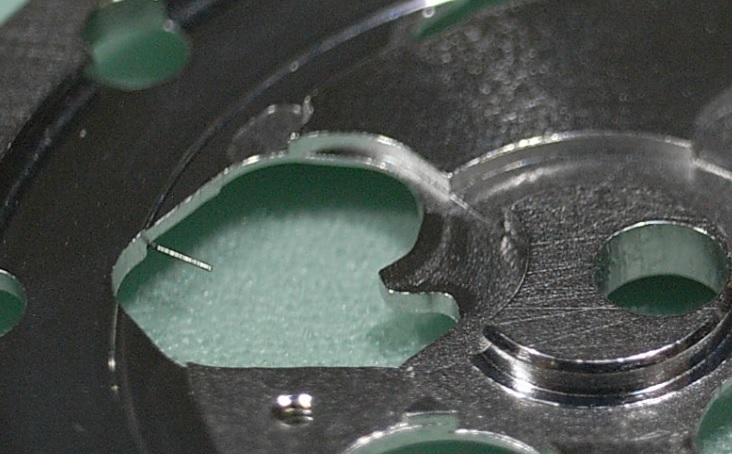
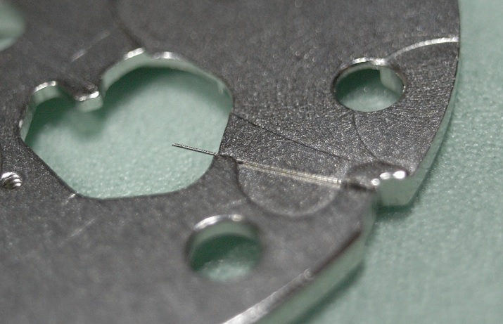
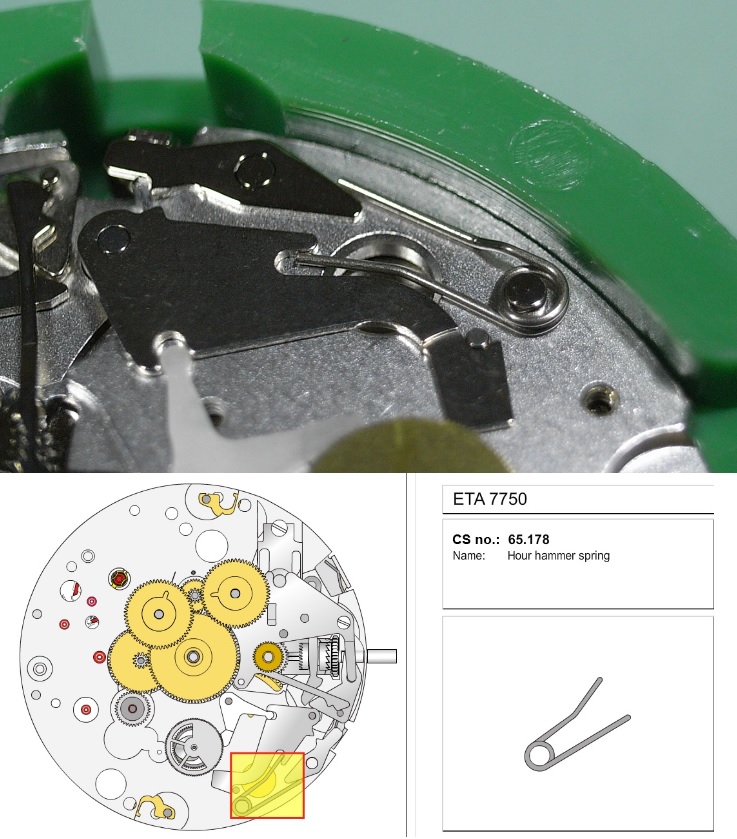
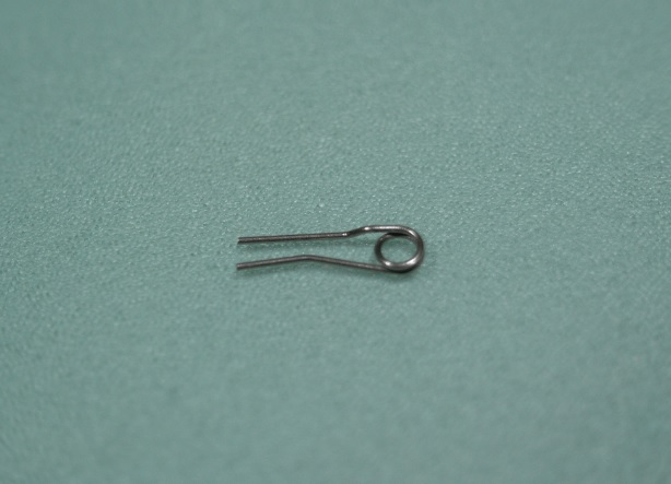
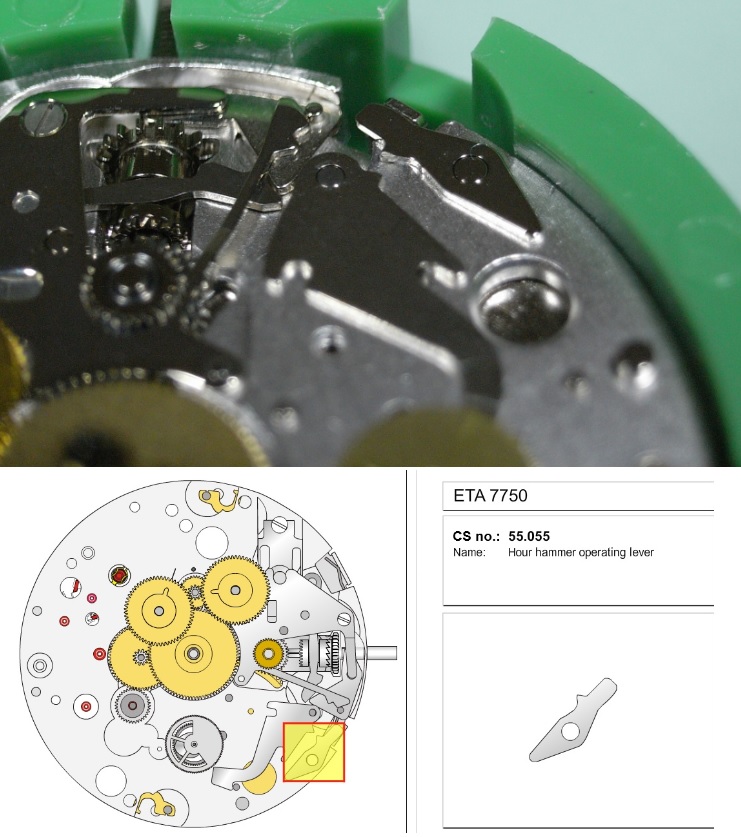
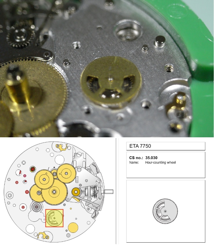
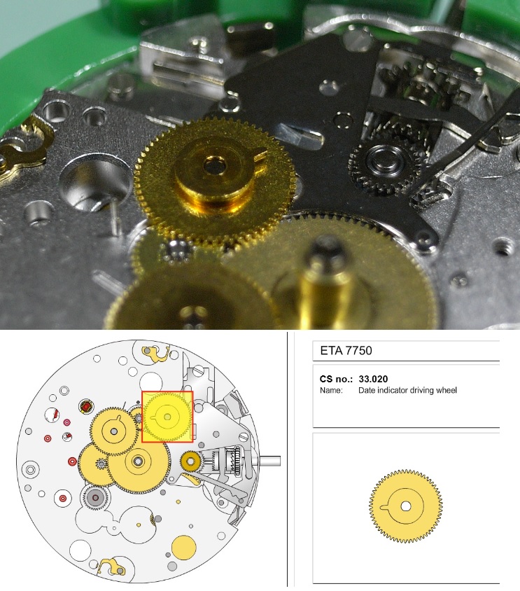
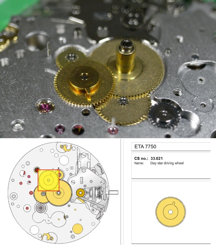
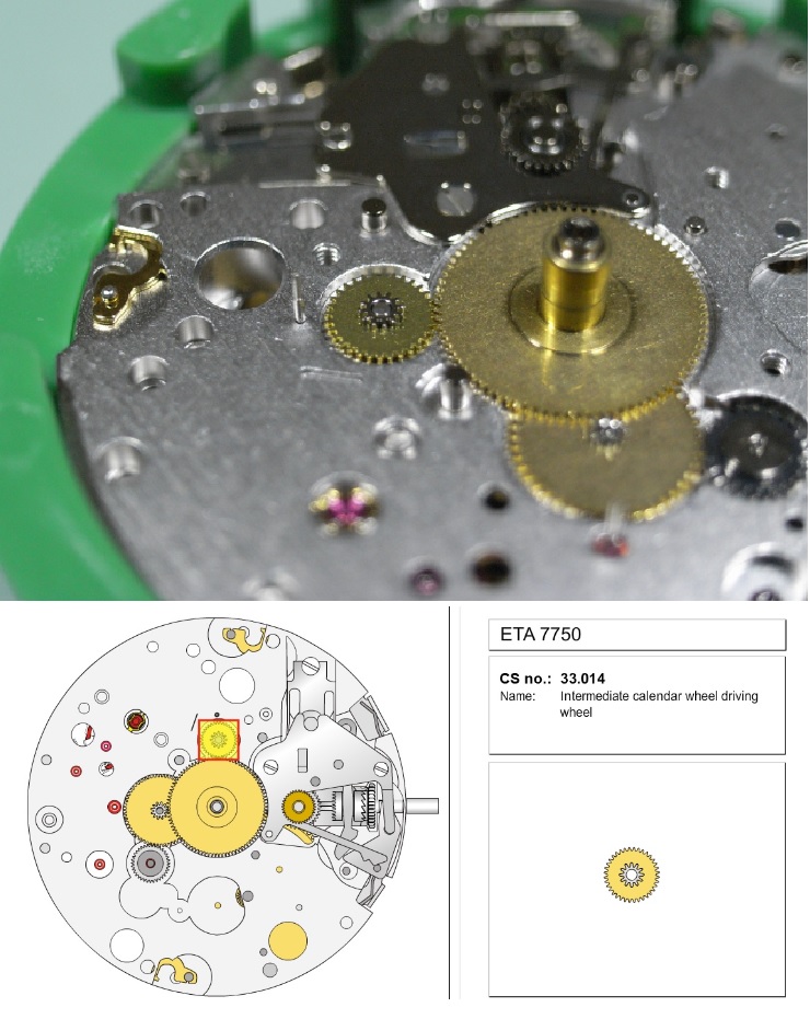
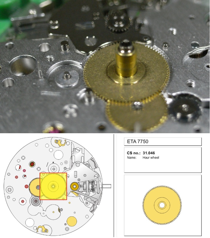
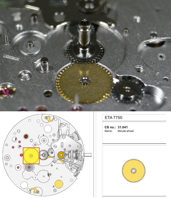
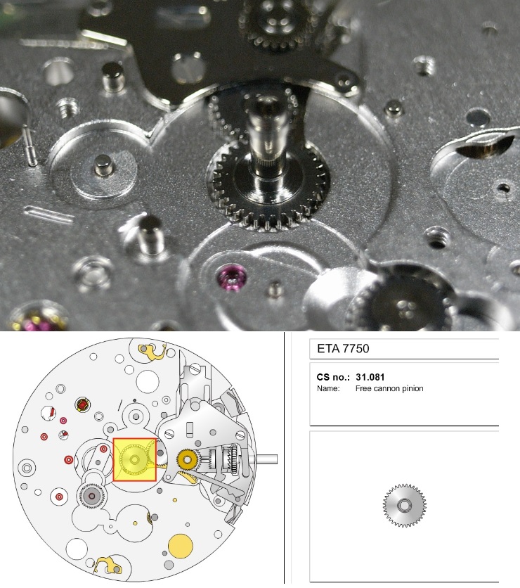
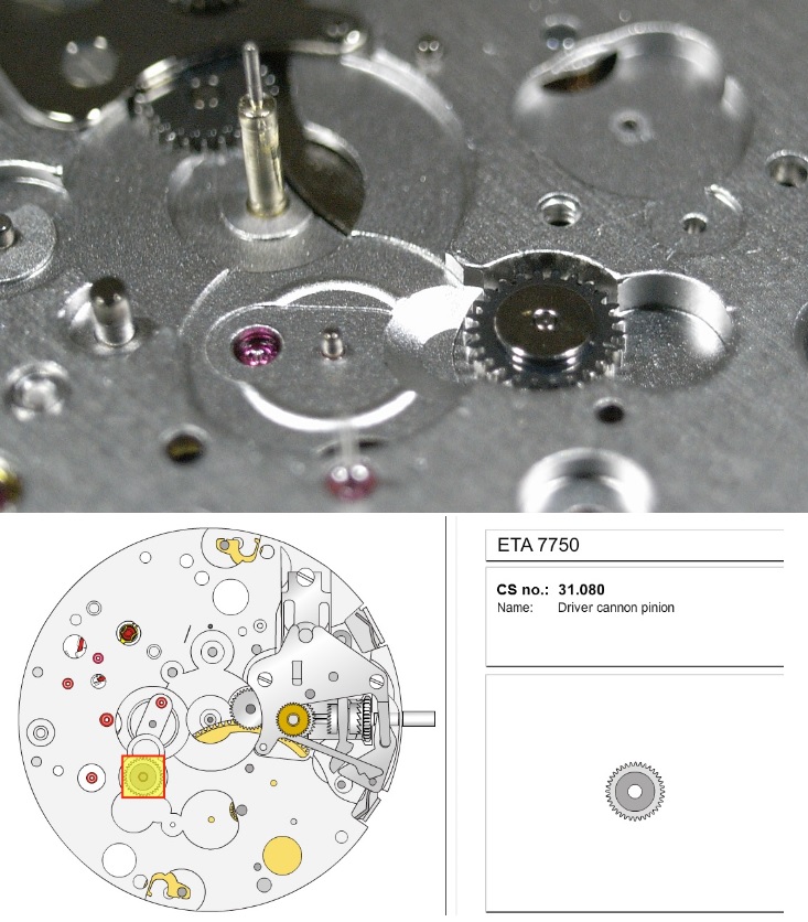
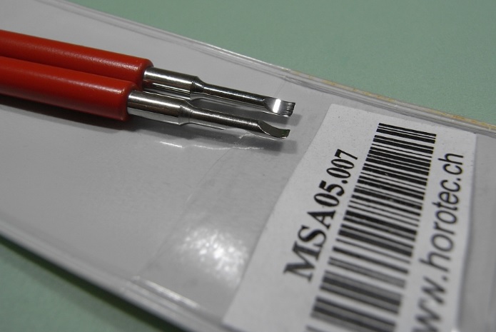
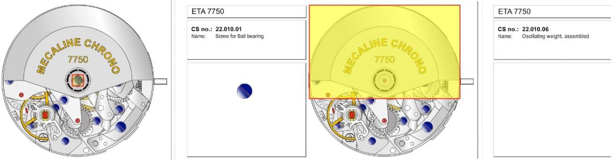
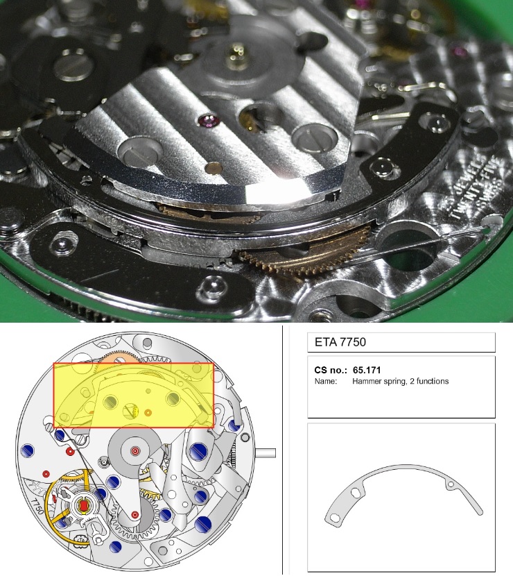
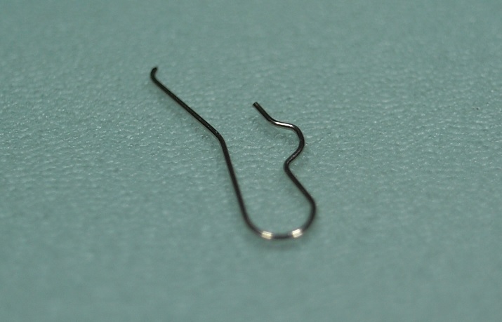
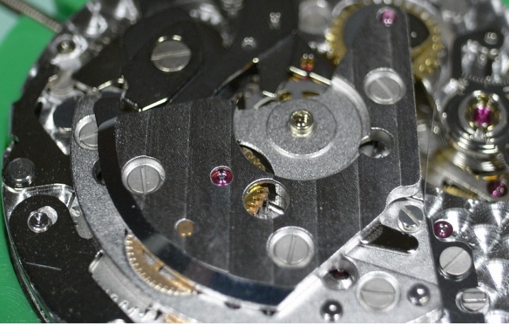
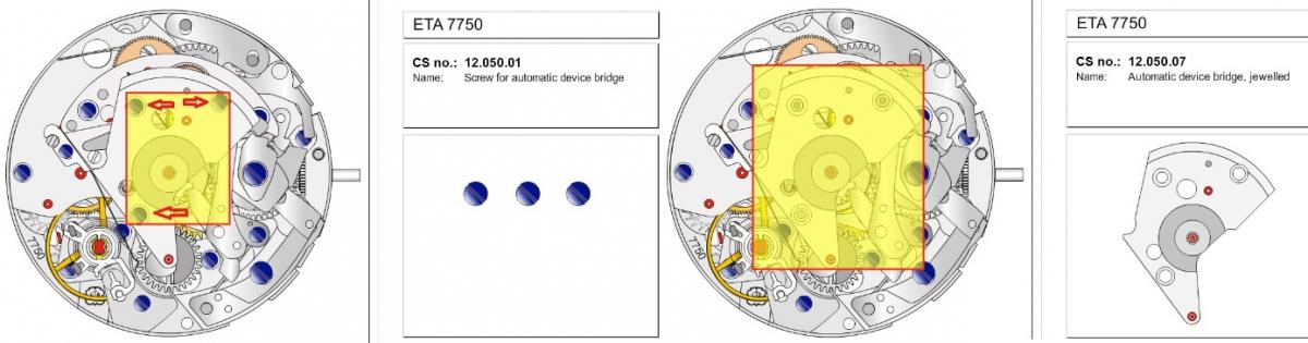
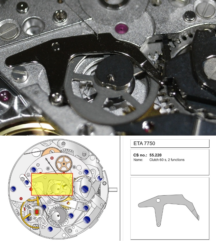
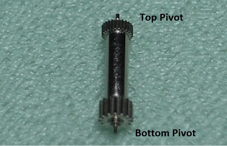
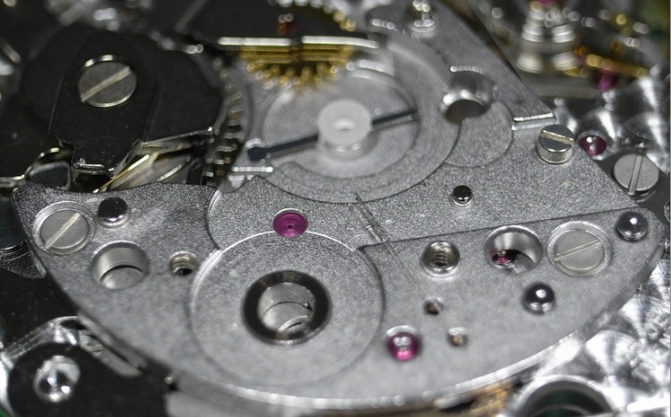
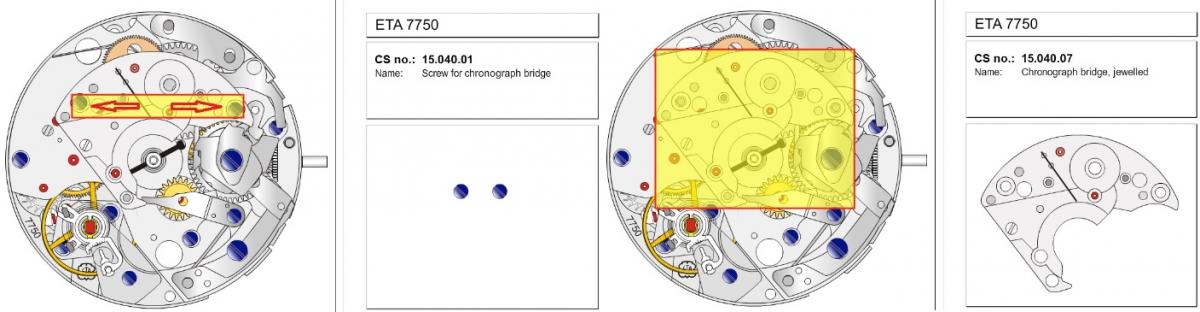
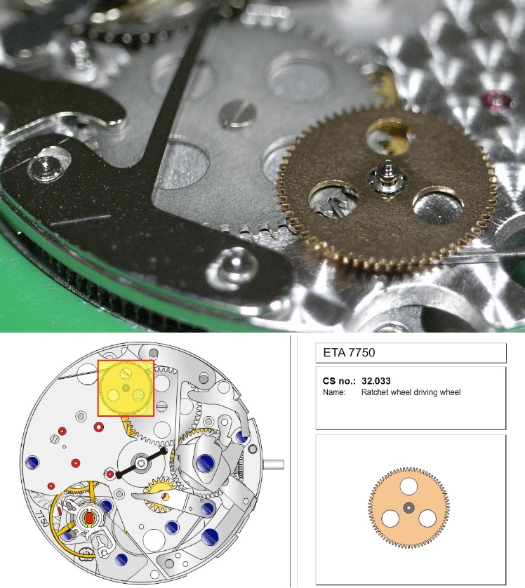
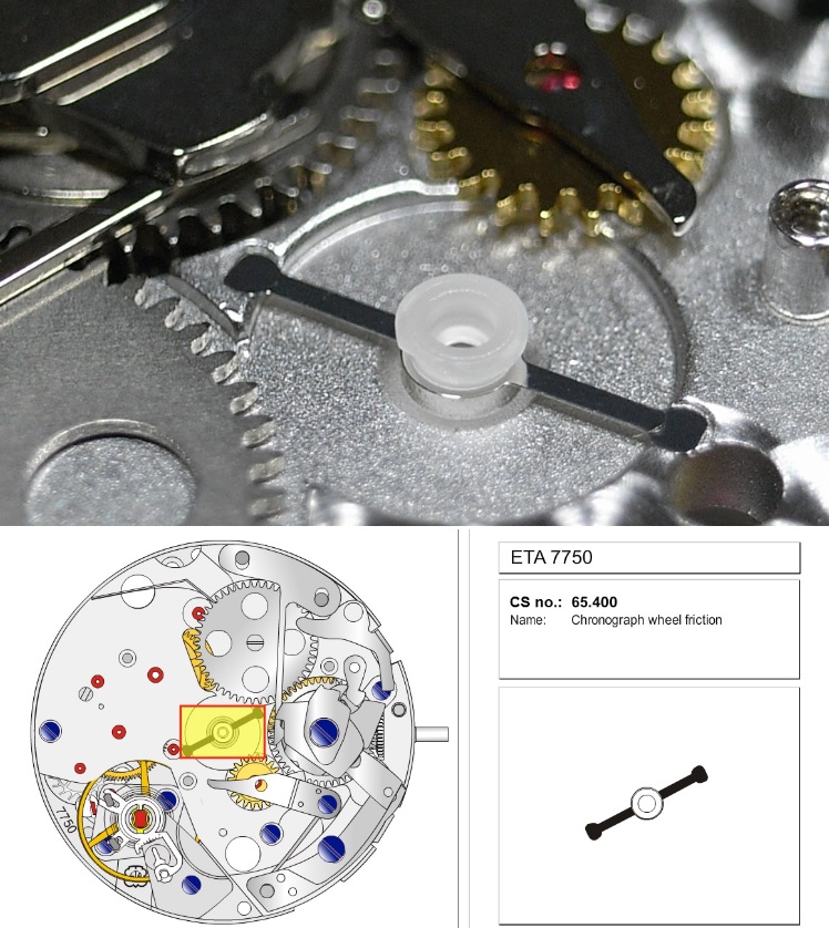
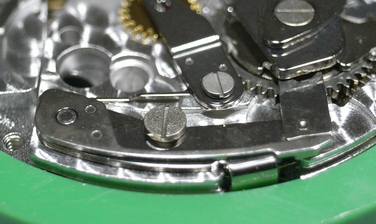
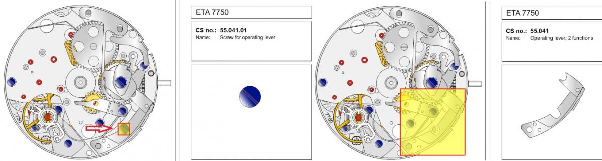
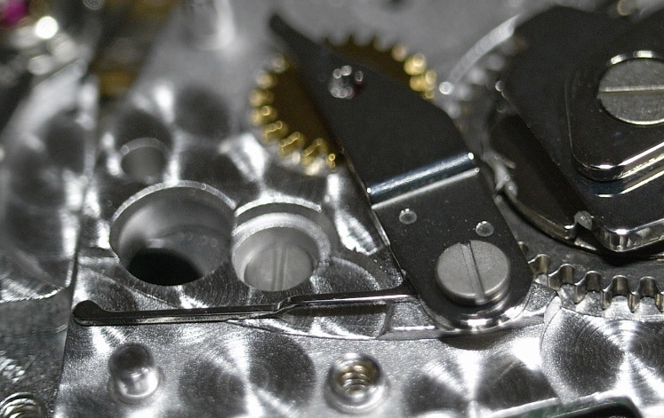
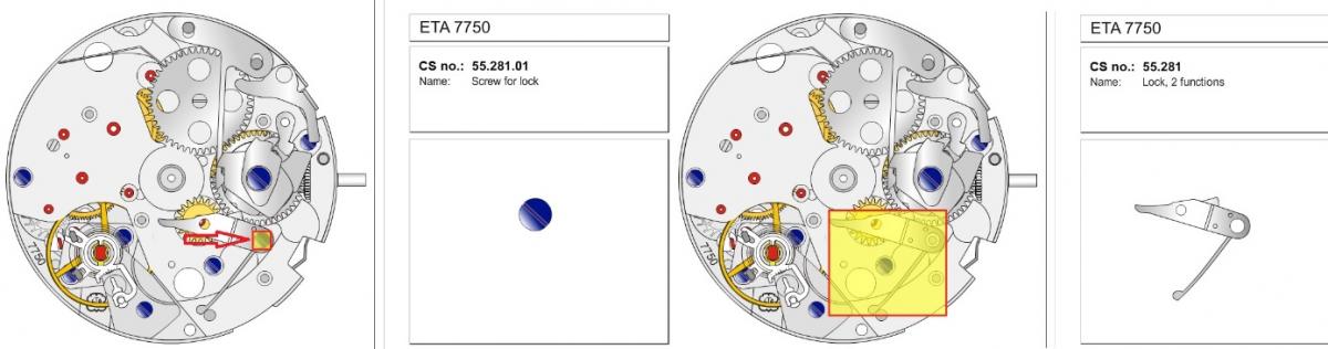
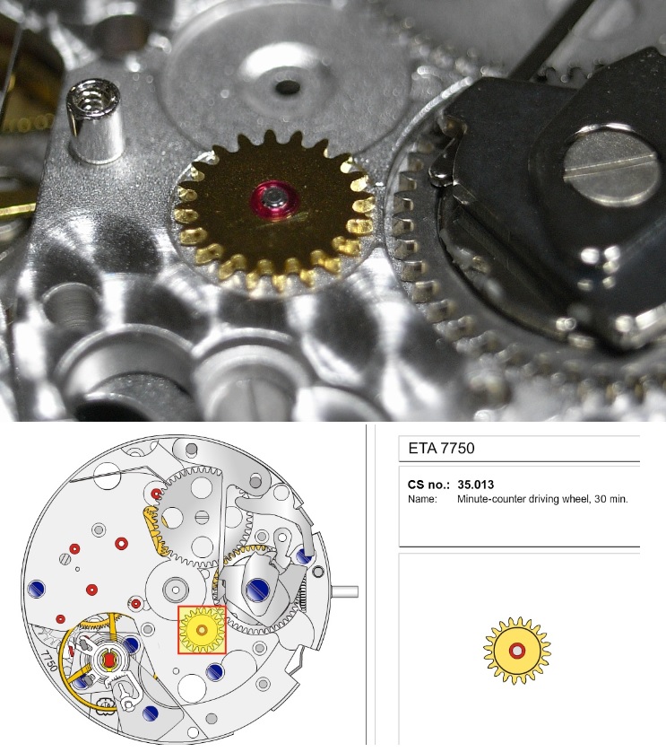
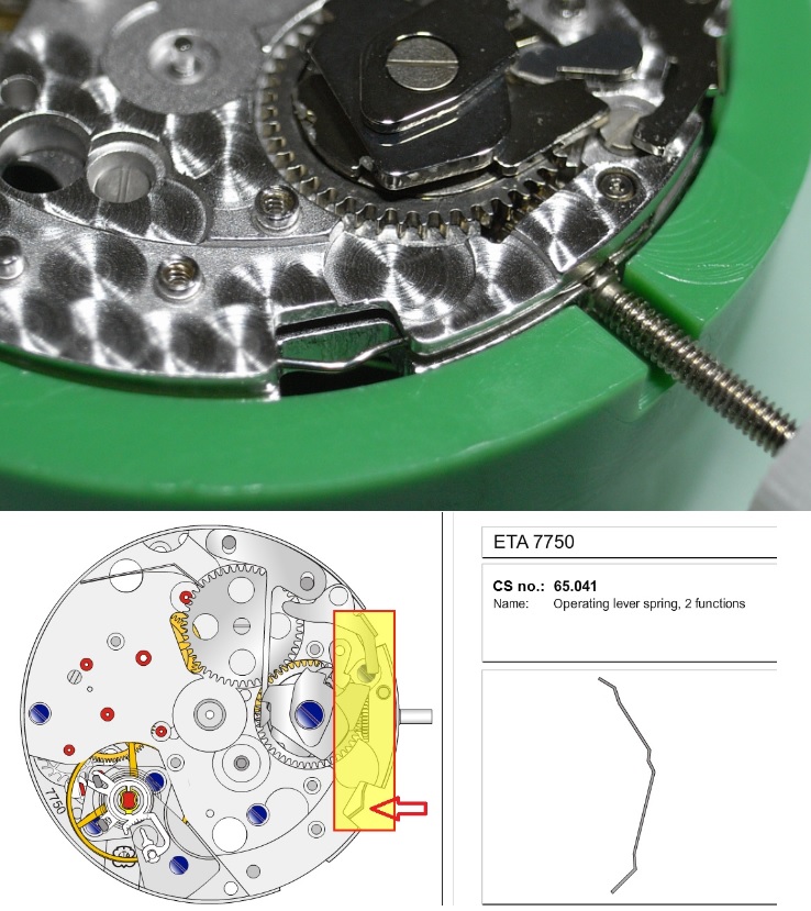
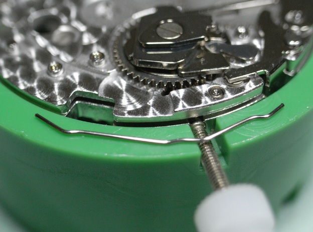
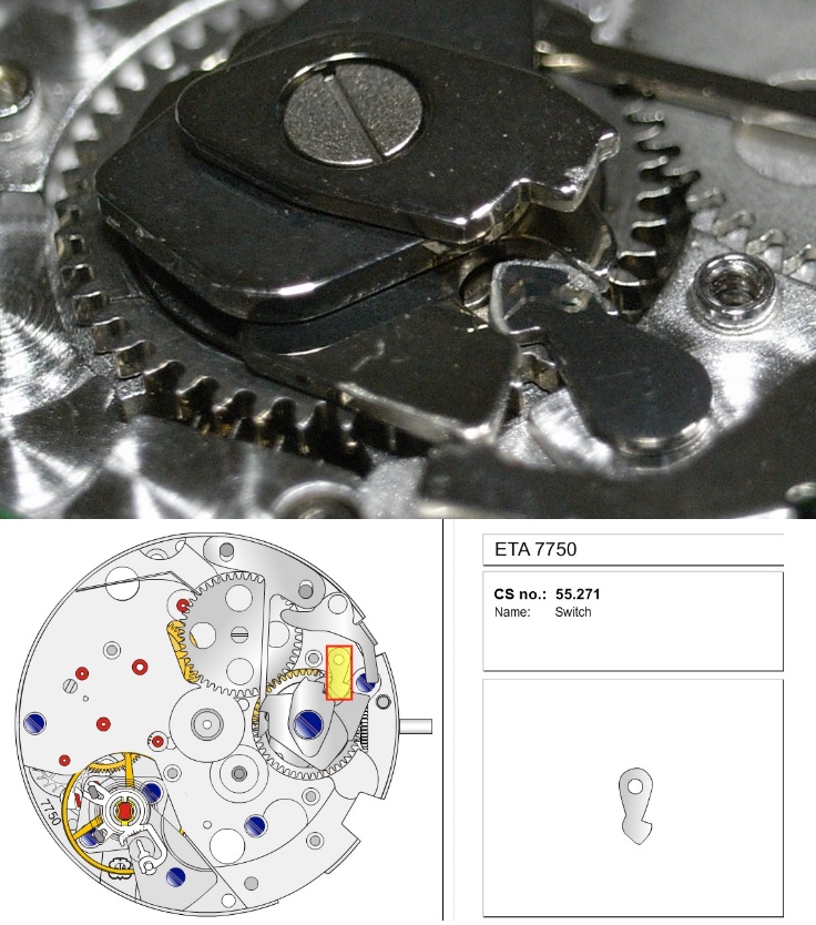
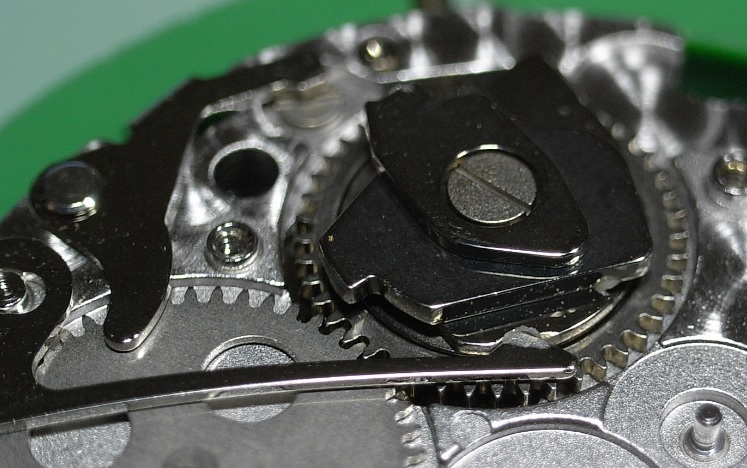
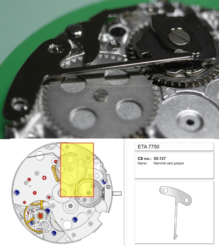
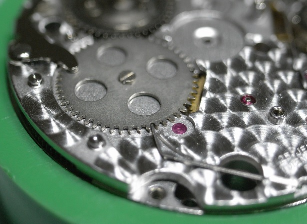
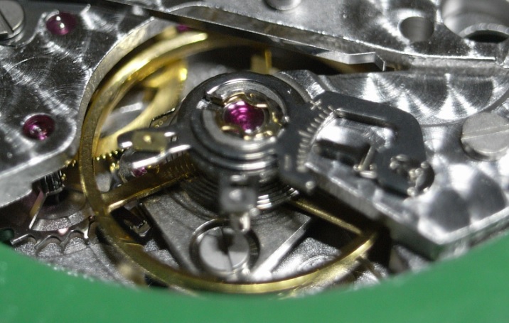
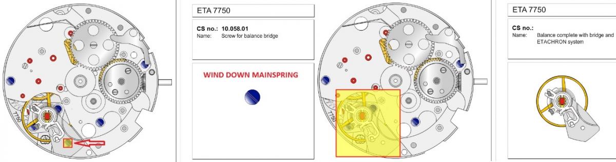
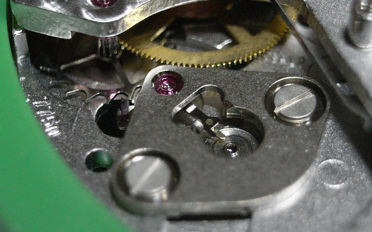
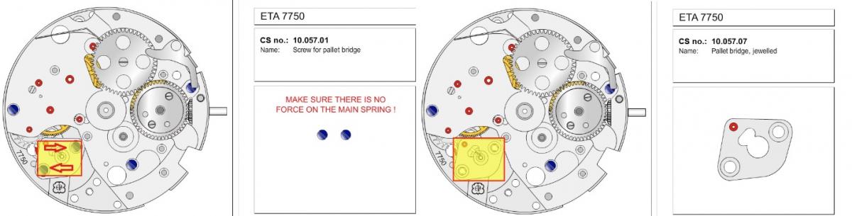
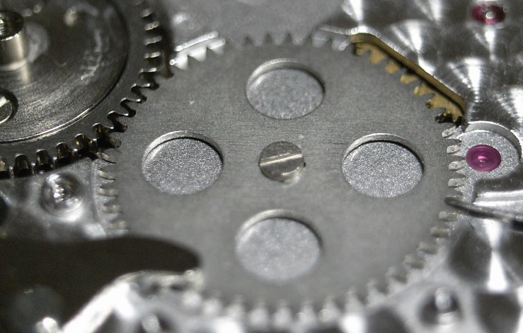
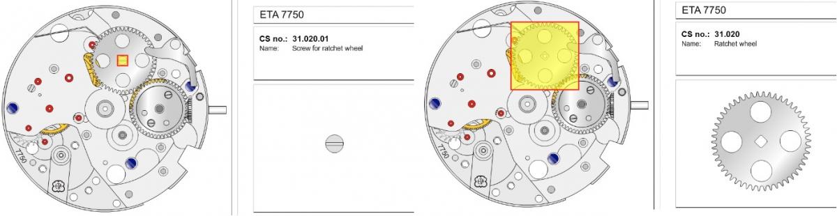
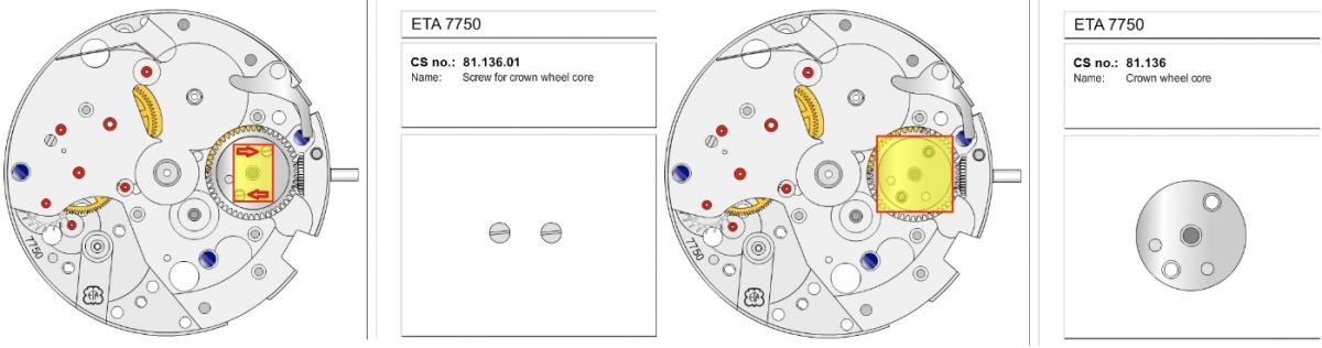
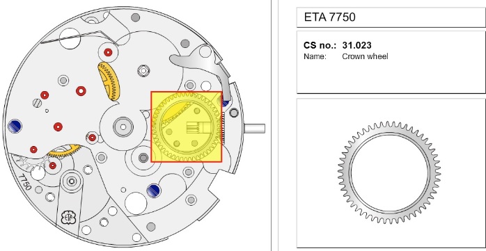
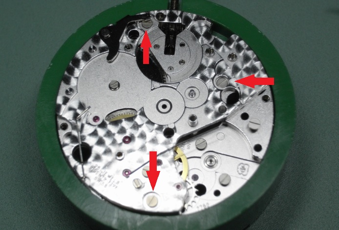
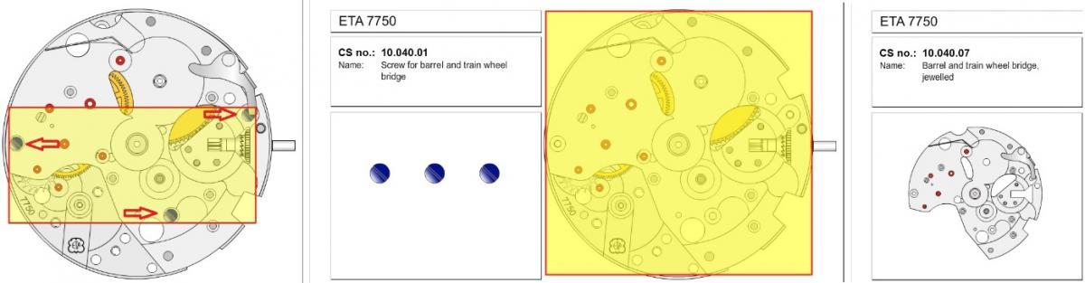
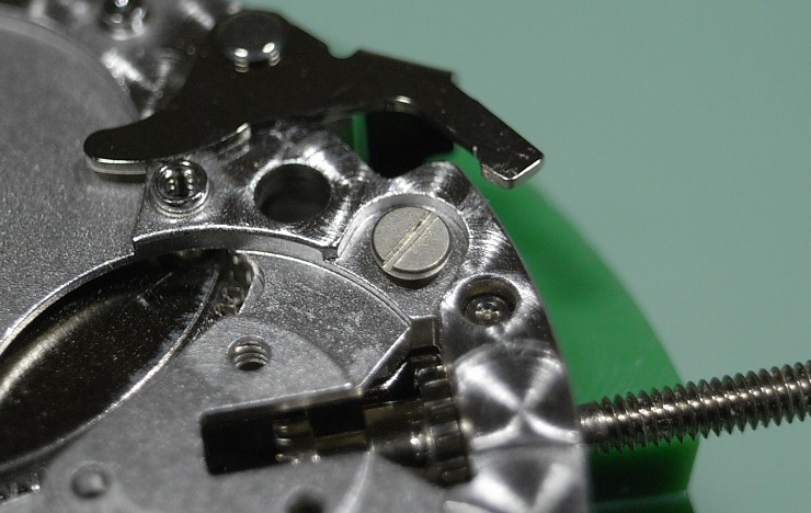
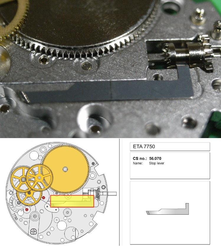
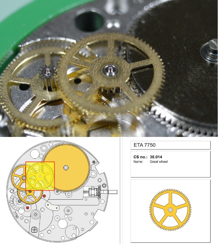
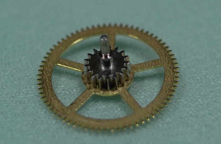
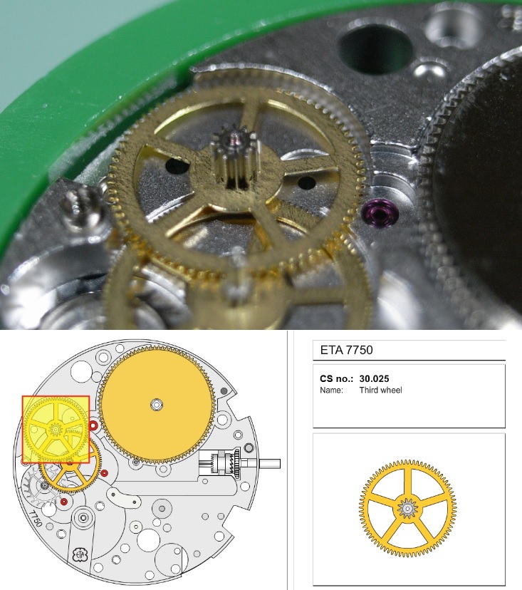
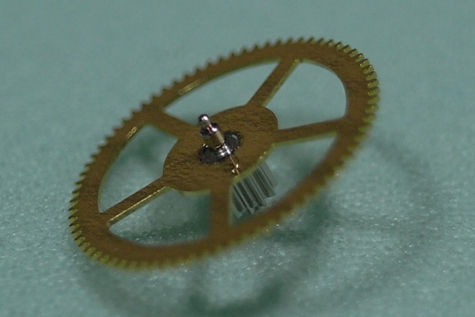
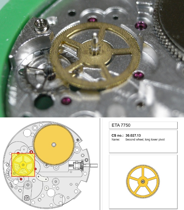
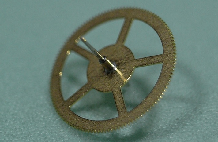
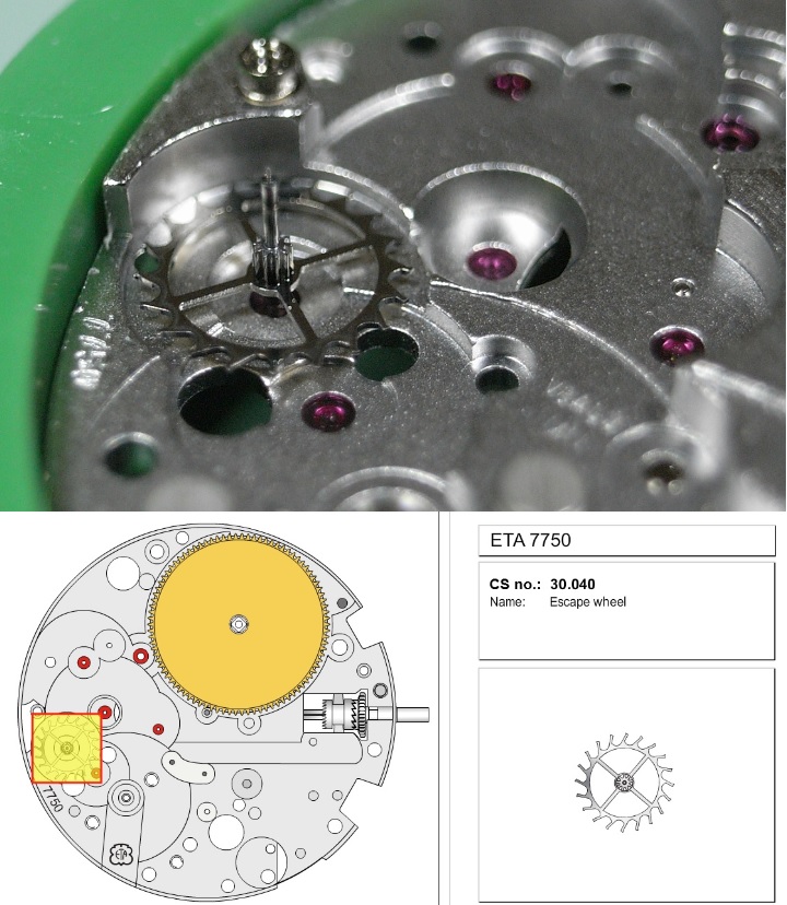
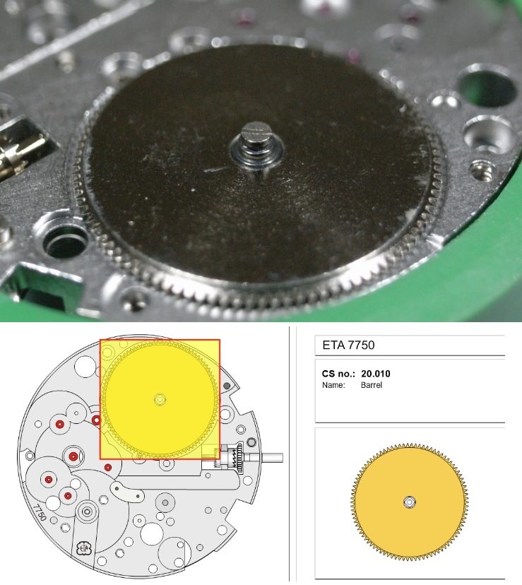
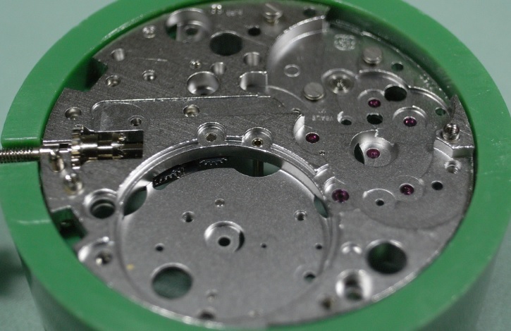
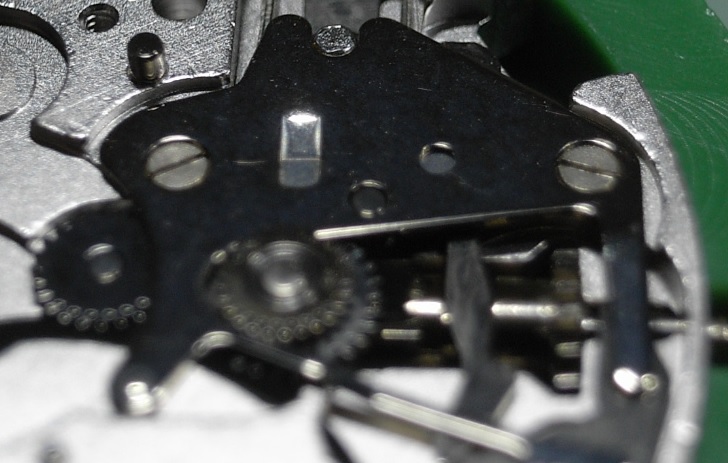
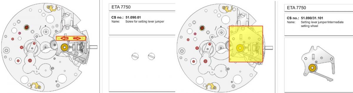
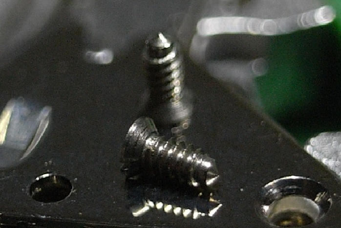
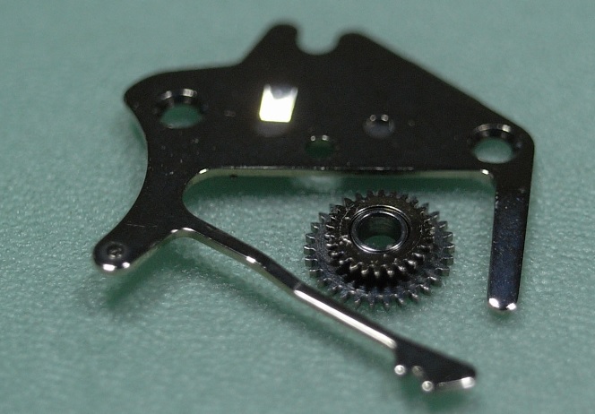
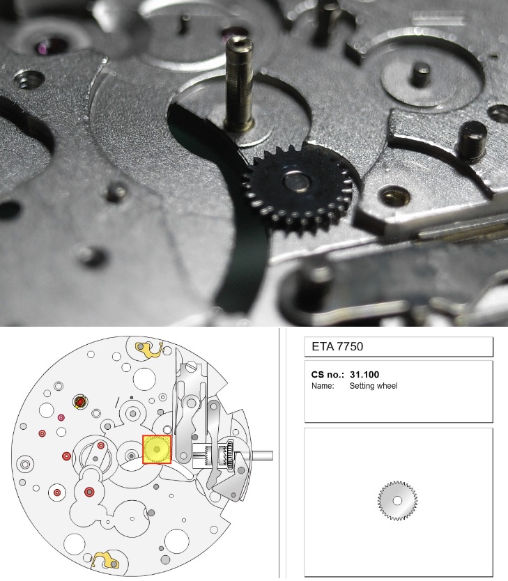
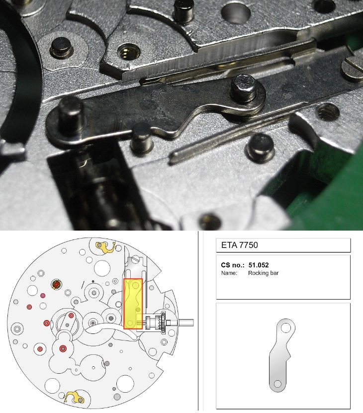
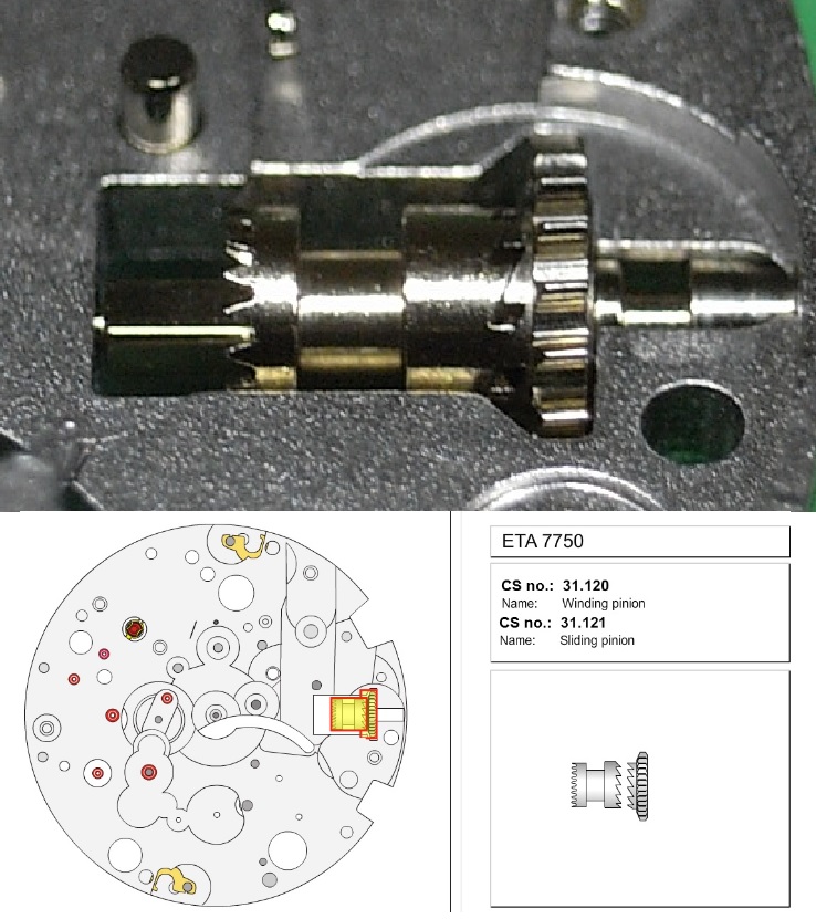
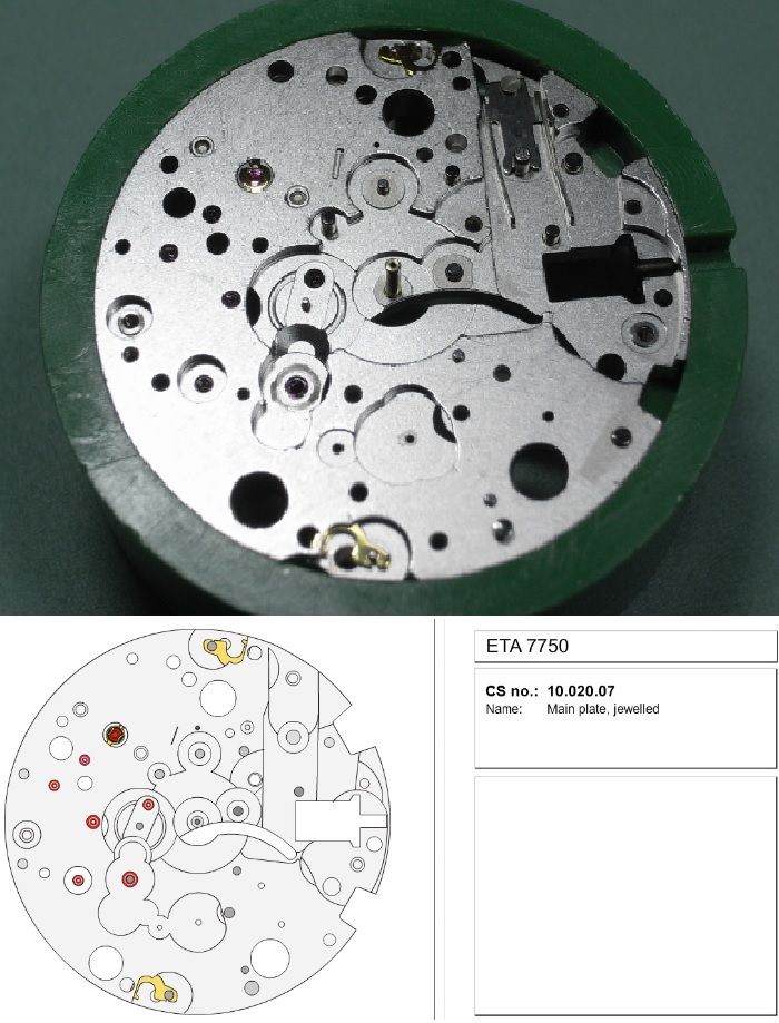
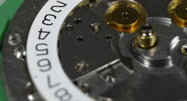
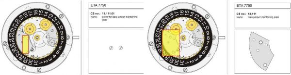
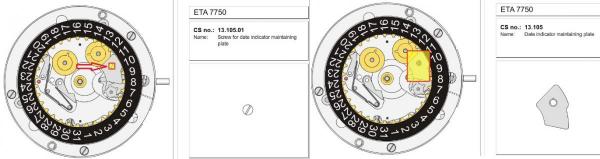
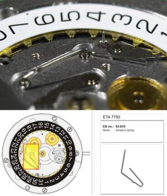
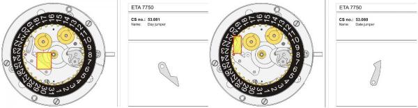
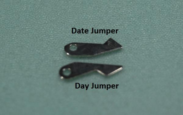
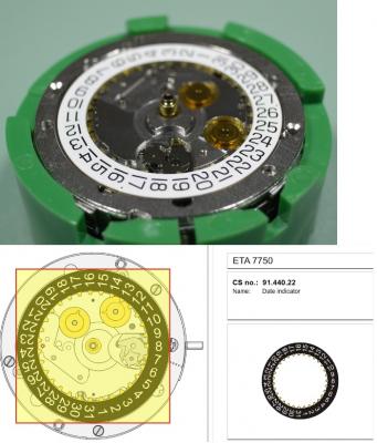
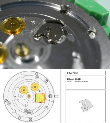
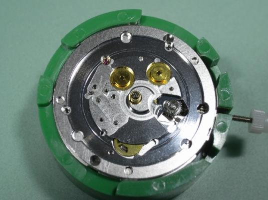
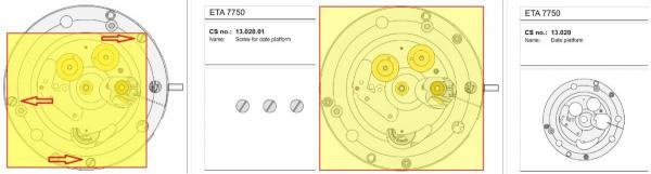
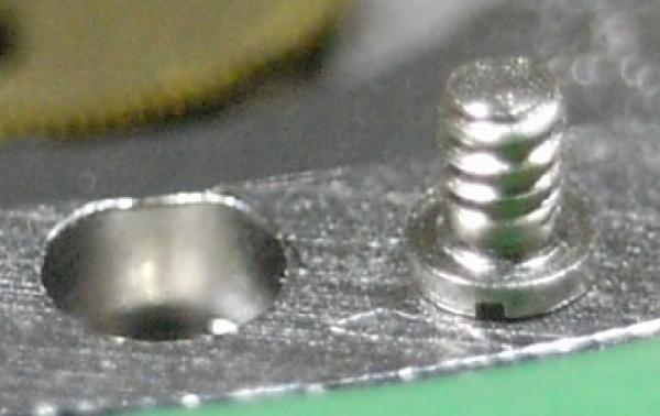
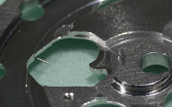
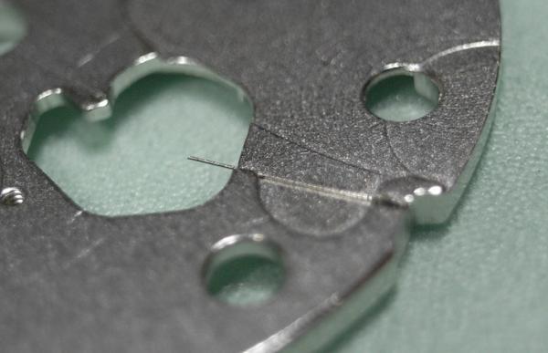
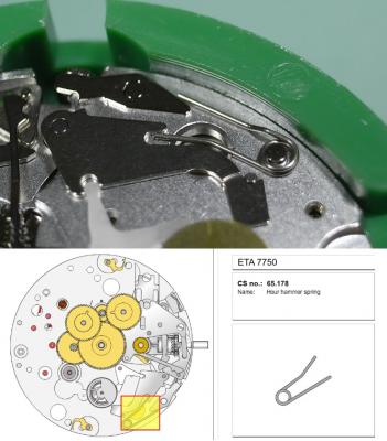
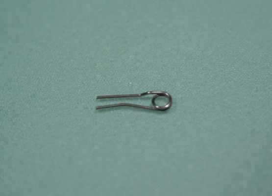
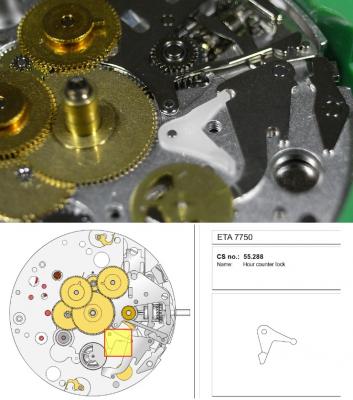
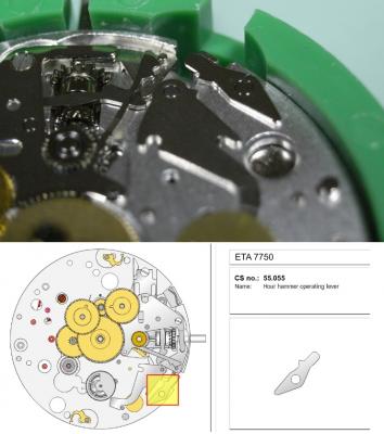
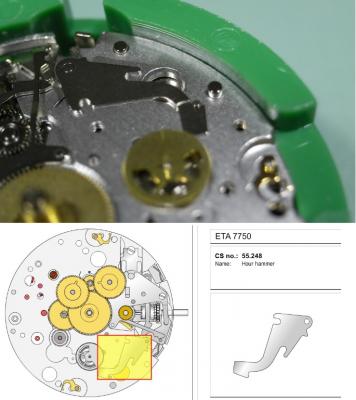
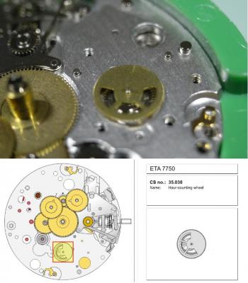
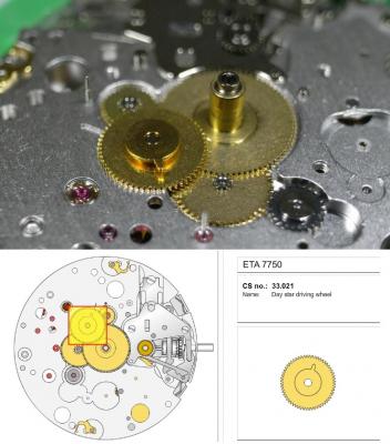
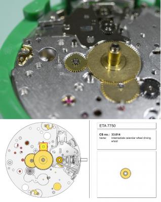
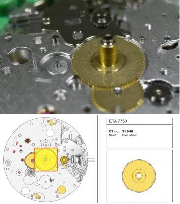
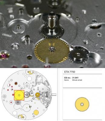
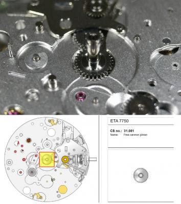
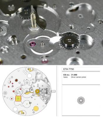
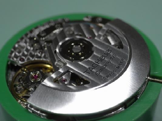
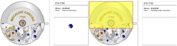
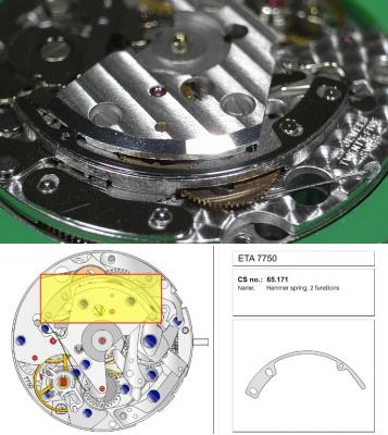
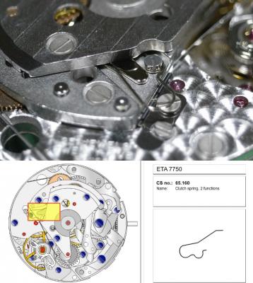
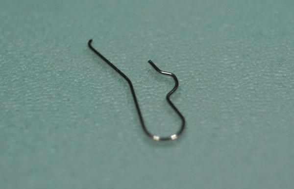
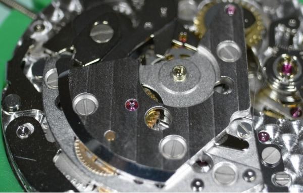
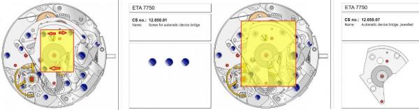
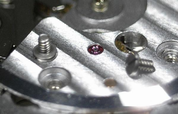
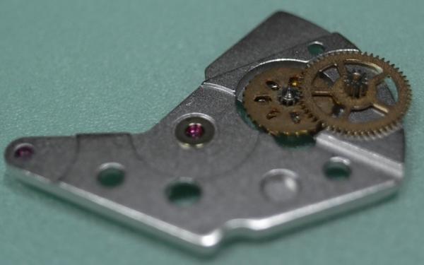
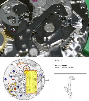
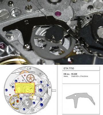
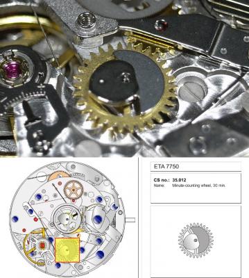
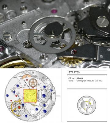
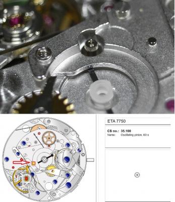
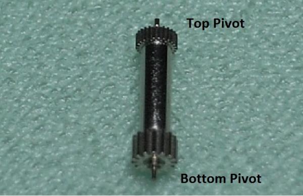
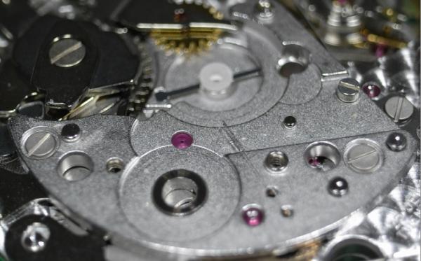
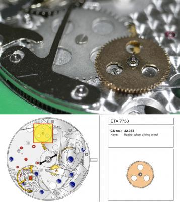
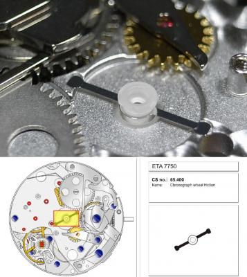
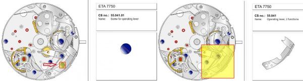
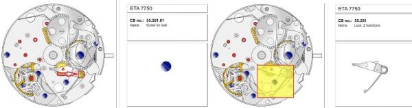
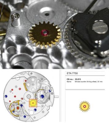
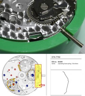
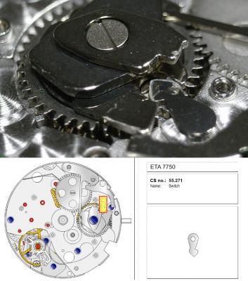
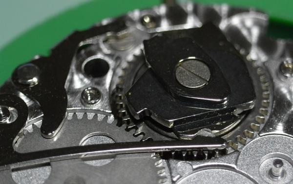
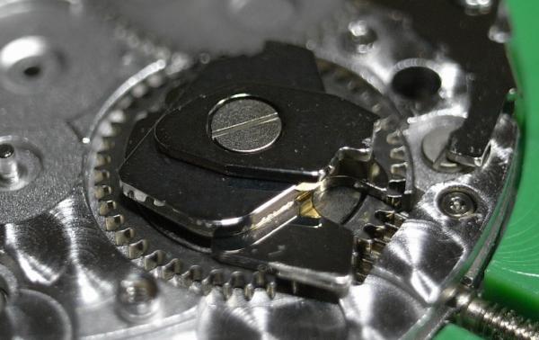
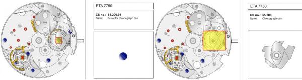
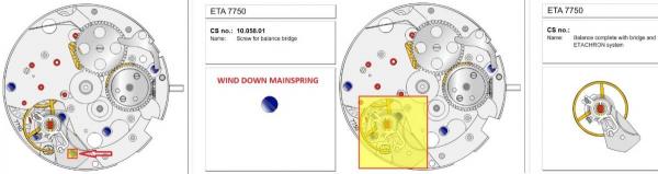
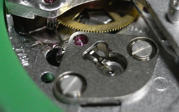
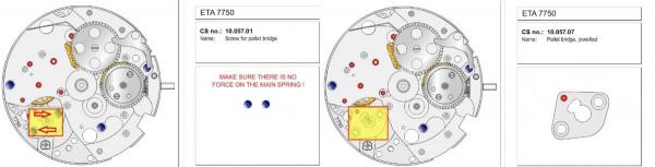
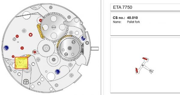
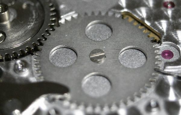
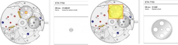
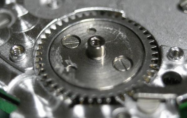
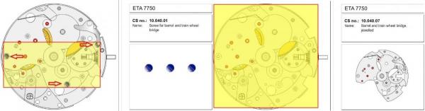
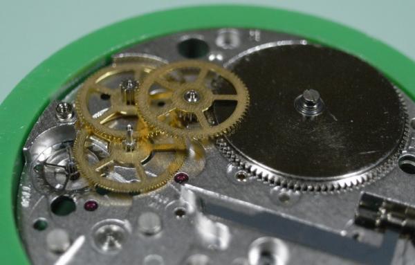
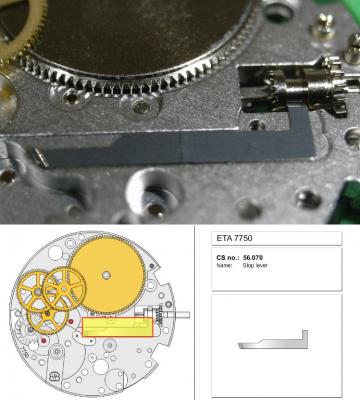
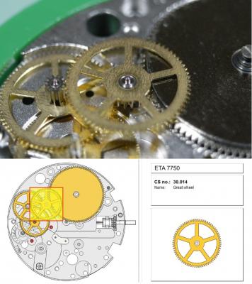
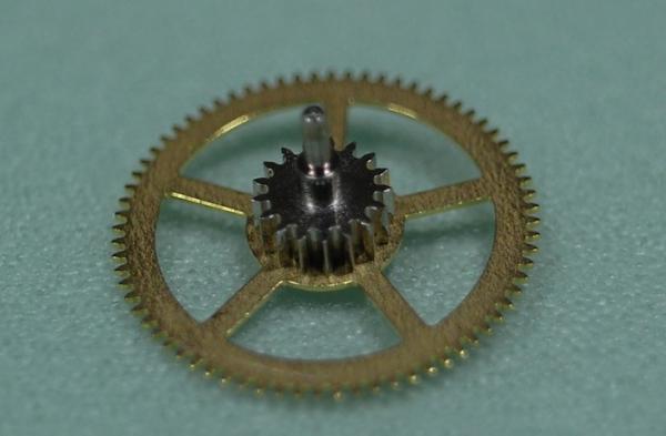
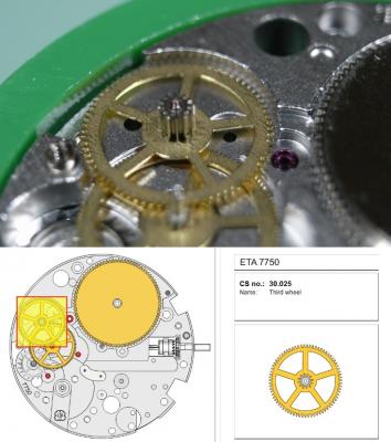
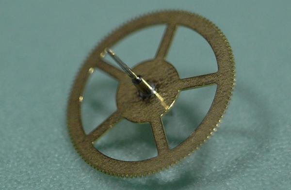
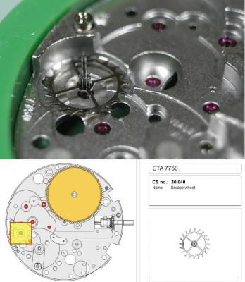
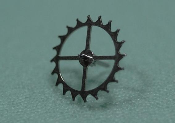
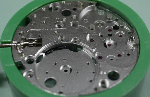
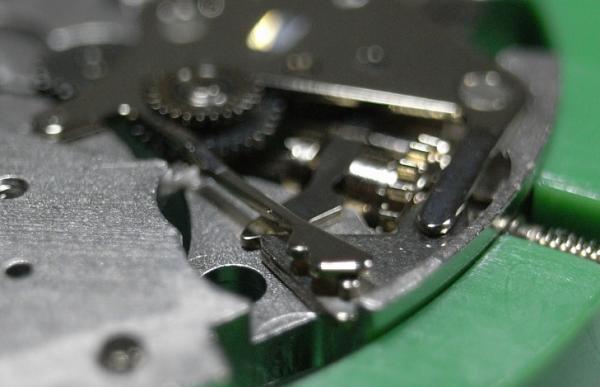
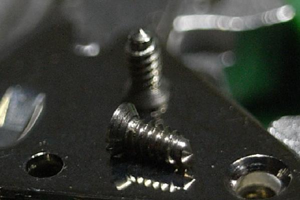
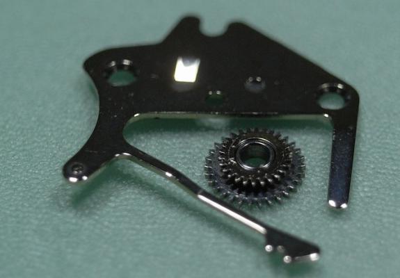
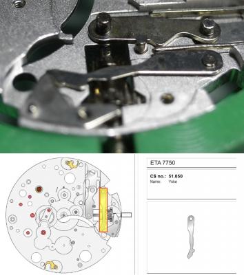
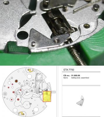
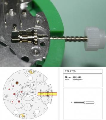
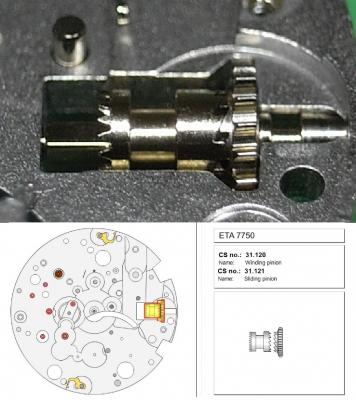
ETA 7750 Service Walkthrough The 7750 was first available in 1974, having been one of the first movements to be designed with the aid of a computer. It's hard to believe that the 7750 is still the industry standard movement for chronographs considering it's history. It was developed over 40 years ago by Valjoux, who was then a legendary movement maker that was part of the giant ASUAG conglomerate. But by the end of 1975 production was stopped due to the onslaught of the Quartz Era, and the 7750, along with many other mechanical calibers, was abandoned. Industry demand for this movement was so low that the stock produced in that 1 year manufacturing lasted until 1982! Such was the devastation of cheap Japanese produced quartz watches to Swiss manufactures. History may have forgotten the 7750 except for the local management at Zenith who ignored the orders by Valjoux to destroy the dies and equipment used to manufacture the 7750, instead hiding the equipment away from corporate eyes. You can find many more fascinating facts about this caliber online, and it's well worth the read. ................................................... This walkthrough will be very detailed, and I hope this will give people the courage to tackle this movement. I've serviced quite a few calibers, and this is one of the most beautiful, with a very logical layout. ETA7750 Tech.PDF If you have built your skills with basic movements, and become proficient in servicing them, I would highly recommend this movement to be your first chronograph to tackle. Lets begin. DEMAGNETIZE THE MOVEMENT BEFORE DISASSEMBLY. Remove the Day Indicator and store it in a safe place where it won't be damaged. Unscrew (0.8 Driver) the Jumper Maintaining Plate and remove it. Do the same for the Date Indicator Maintaining Plate Carefully remove the Jumpers Spring, holding it with a piece of pegwood so it doesn't ping away. Next remove the jumpers for the day and date. The jumpers differ from one another, so here is a reference photo so you can see the difference. Remove the Date Indicator and place it in a safe place where it won't be damaged. The last piece to remove on the Date Platform is the Double Corrector Now unscrew (1.4 Driver) the Date Platform and gentle pry it from the movement. Be careful when removing this plate, as there is a fine spring pressed into the plate that can be easily damaged. Here is a reference photo of the screws that hold the Date Platform. Remove the Hour Hammer Spring, once again using the pegwood to hold the spring while removing the tension. Here is a reference photo of the correct orientation of the spring. Remove the Hour Counter Lock. Remove the Hour Hammer Operating Lever. Next is the Hour Hammer, be careful when removing this item so as not to damage the Hour-Counting Wheel. Now remove the Hour-Counting Wheel. Remove the Date Indicator Driving Wheel Remove the Day Star Driving Wheel Then remove the Intermediate Calendar Driving Wheel Remove the Hour Wheel Then the Minute Wheel Remove the Cannon Pinion, which does not require a puller. The last component to be removed on this side of the Main Plate is the Driver Cannon Pinion. To lift the Driver Cannon Pinion I used what Mark used, a set of hand lifter from Horotec (MSA05.007); but you can also use a Presto Tool (30636-1) which will also work well. The dial side of the movement is now complete disassembled. Flip the movement over and unscrew (1.5 Driver) the Oscillating Weight. To remove the Hammer Spring lift it up gently over the automatic work and move it inwards. This will move the tail of the spring in a clockwise motion to the opening in the slots, which will free the spring. Slide out the Clutch Spring. Here is a reference photo of this spring, and it's orientation. Remove the screws (1.4 Driver) for the Automatic Device Bridge, and gently pry it loose. Here is a reference photo of these screws for the bridge. Once the Automatic Bridge has been removed, the two wheels for the automatic work are able to be removed. Below is a reference photo of how the sit inside the bridge. We now begin to disassemble the chronograph section of this movement. Begin with removing the Hammer, 2 Functions. Next remove the Clutch 60s, 2 Functions. Then remove the Minute-counting Wheel, 30min. Remove the Chronograph Wheel 60s, 30min. Gently lift out the Oscillating Pinion, 60s. Here is a reference photo of the orientation of this pinion. Unscrew (1.4 Driver) the Chronograph Bridge and gently pry it off the Train Wheel Bridge. Remove the Ratchet Driving Wheel. Remove the Chronograph Wheel Fiction. Unscrew (1.4 Driver) the Operating Lever, 2 Functions. Unscrew (1.4 Driver) the Lock, 2 Functions. Next remove the Minute-counter Driving Wheel, 30min. Slide out the Operating Lever Spring, 2 Functions. This spring can be fitting in both directions; but only 1 way is correct. Here is a reference photo of it's correct orientation. Remove the Switch. Here I digress from the order the SwissLab document illustrates the order of removal. They show to remove the Chronograph Cam before removing the Hammer Cam Jumper. This in my opinion is not the best way, as all the force from the jumper is pressing on the cam whilst your trying to remove it, and could lead to damage. Instead I move the Chronograph Cam until it reaches the notch as shown in the photo below. Then lift the Hammer Cam Jumper up to the top of the Chronograph Cam, which will release it's tension. Then, just as you removed the previous hammer, rotate the jumper to the opening in the slots, which will free the spring. Now you can unscrew (1.4 Driver) and remove the Chronograph Cam safely without tension on it. RELEASE THE MAINSPRING TENSION Once the tension has been released, unscrew (1.4 Driver) and remove the Balance Cock. Then unscrew (1.4 Driver) the Pallet Bridge and remove the bridge and Pallets. Unscrew (1.2 Driver) and remove the Ratchet Wheel. Then remove the Crown Wheel. Unscrew (1.4 Driver) the Train Wheel Bridge and gently pry it off the Main Plate. Note that one of the screws is under the Operating Lever. This needs to be moved out of the way to access this screw. The last level of this movement contains the train. Here is a reference photo of the wheel locations. Remove the Stop Lever. Remove the Great Wheel. Here is a reference photo of the underneath of this wheel. Remove the Third Wheel. Here is a reference photo of the underneath of this wheel. Remove the Second Wheel. Here is a reference photo of the underneath of this wheel. Note this has the long lower pivot. Remove the Escape Wheel. Here is a reference photo of the underneath of this wheel. Then remove the Barrel. This completes the removal of the train. Flip the movement over so we can complete the disassembly by removing the keyless work. Firstly, release the tension from the Setting Lever Jumper. Then unscrew (1.2 Driver) and remove the Setting Lever Jumper. These are unique screws with pointed ends, and below is a reference photo of them. This will also remove the Intermediate Setting Wheel. Next remove the Setting Wheel Then remove the Yoke. Remove the Setting Lever. Remove the Rocking Bar. Now pull out the Stem. Once the Stem is removed the Winding and Sliding Pinion should fall out of the movement onto your work mat. Disassembly of the 7750 is now complete If you've come this far, congratulation on completing the disassembly. Make sure you pegwood all the jewels and reinstall the Balance back onto the movement for cleaning. Assembly of the movement will be posted as soon as I complete the write-up.


 1 point
 -
Welcome I'm a UK newbie too. Cheers Neil1 point
-
I wouldnt recommend removing them, there are too many variables to watch dial cleaning, what is the compostion of the dial is it laquered? is the printing on top of the laquer or underneath, what has caused the marks is it oxidisation? has the laquer been affected by damp or even oil. Can the laquer be removed without dragging the printed details with it. options: live with it, a good idea in my opinion the dial although not perfect looks acceptable to me you have neither improved or worsend the dial by opting to do this Look for a dial on ebay to replace the one you have, have the dial profesionally restored, expensive but you will end up with a mint looking dial, but that in my eyes would be very obvious to any collector and many would actually consider this of detriment to the watch, Have a go yourself and for ever regret the day you tried any of the snake oil remedies that can be found on the web. If you are thinking of cleaning it then try it on a very small area first you may get lucky and find a technique that works, but I've searched and never found a satisfactury way to clean light coloured dials on the web, but have seen many lamentable attempts.1 point
-
Depends, from experience, I originally purchased various sizes lots from China, BIG MISTAKE, they perish over time, become brittle, and frey. So I binned the lot and purchased the more expensive option boxsets Swiss ISO type thick from cousinsuk. Its not worth risking a watch water resistance with anything else to be honest. I find the £52GBP box assortment very good quality. https://www.cousinsuk.com/product/o-ring-box-sets1 point
-
Cheers everybody! Sperki thats great, his parents must have great taste [emoji38] Sent from my iPhone using Tapatalk1 point
-
There are nice UV light LED flashlights. The "Black Light" makes lots of stuff light up like jewels and the blue steel springs. Handy to have around. Also those dandy UK made Dyson Vacuums don't run you parts though the impeller before the make it to the dust bin.1 point
-
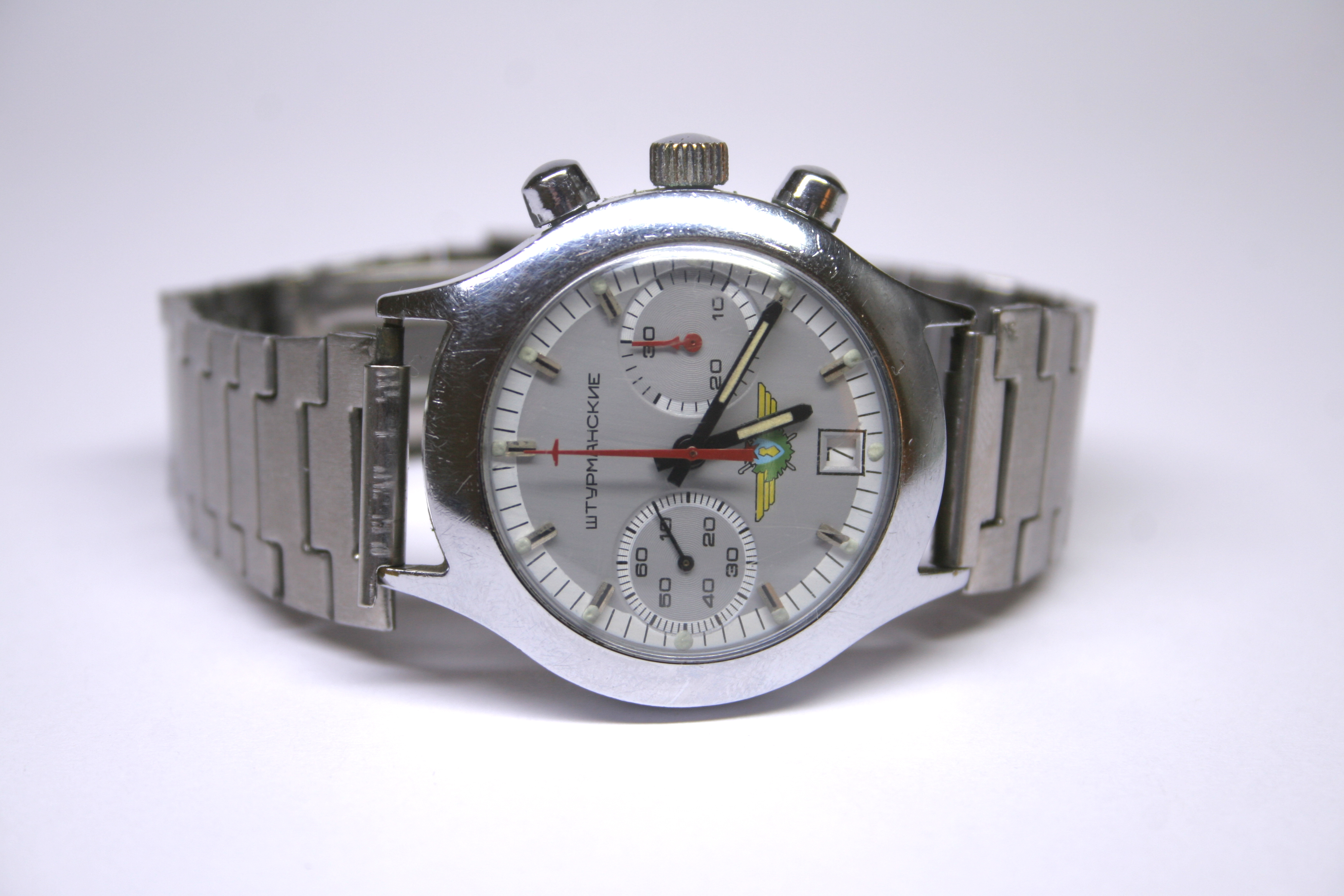
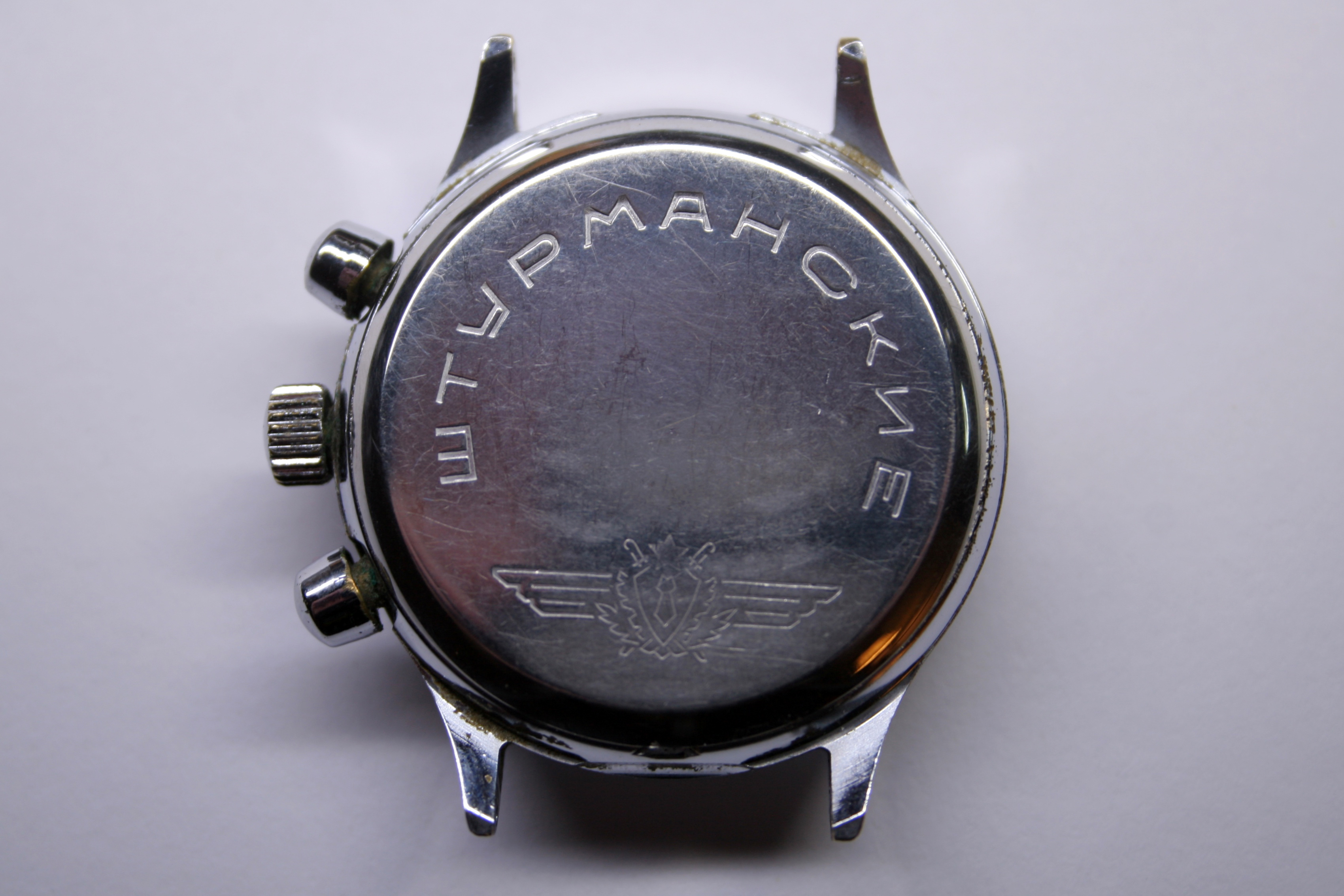
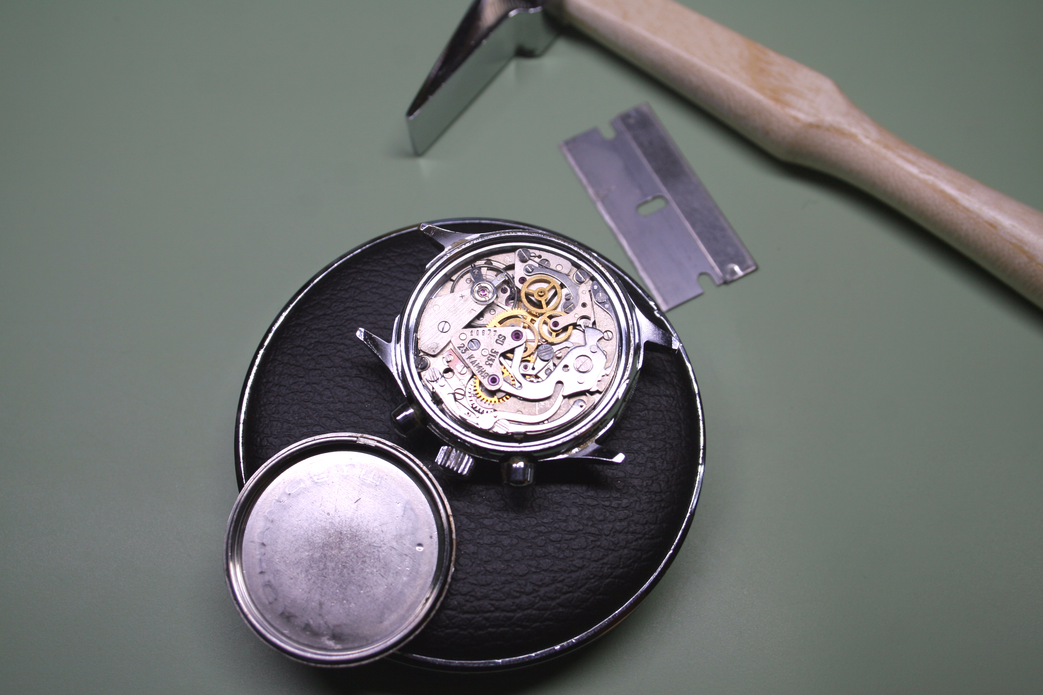
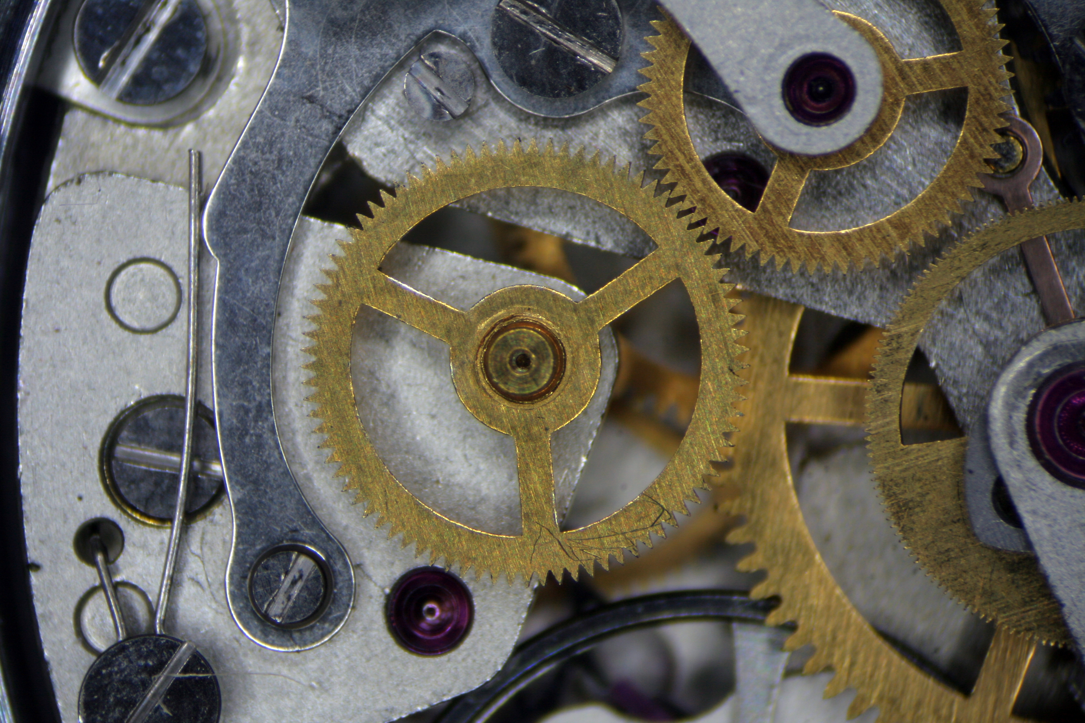
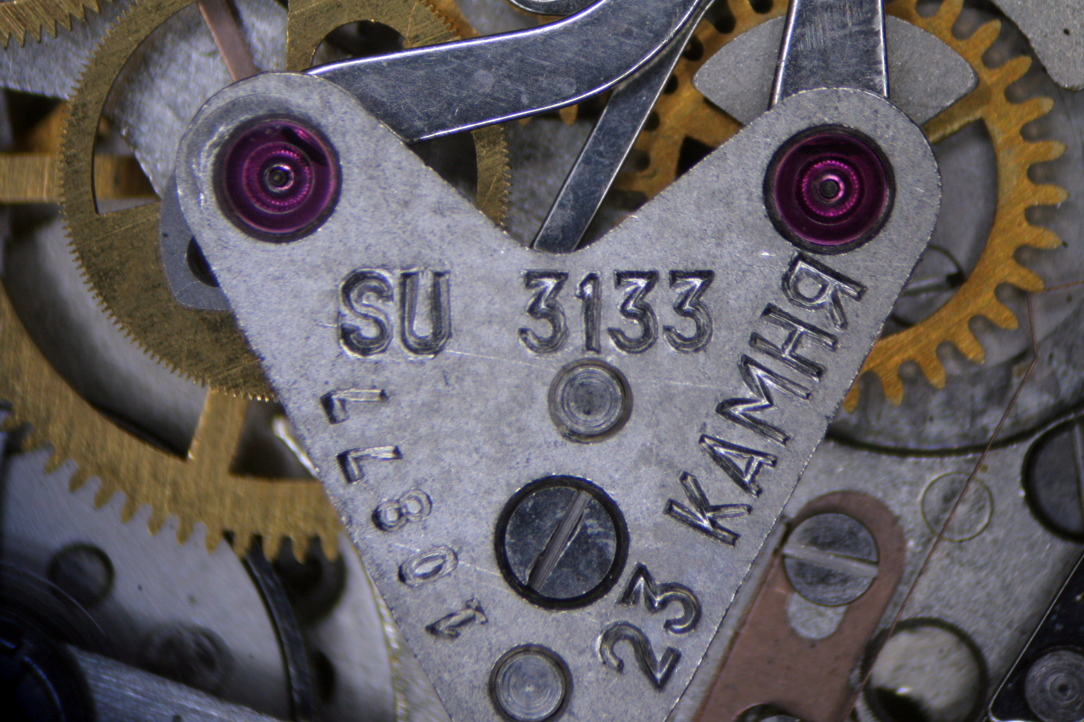
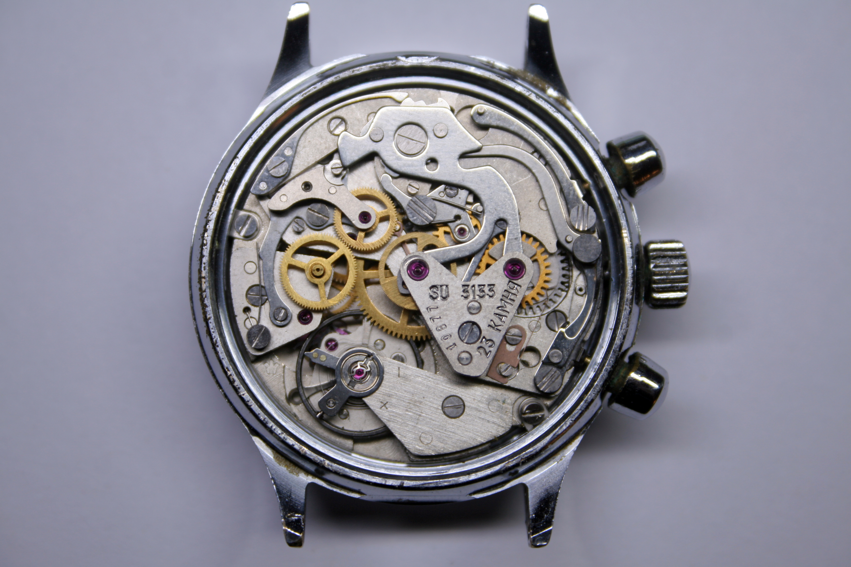
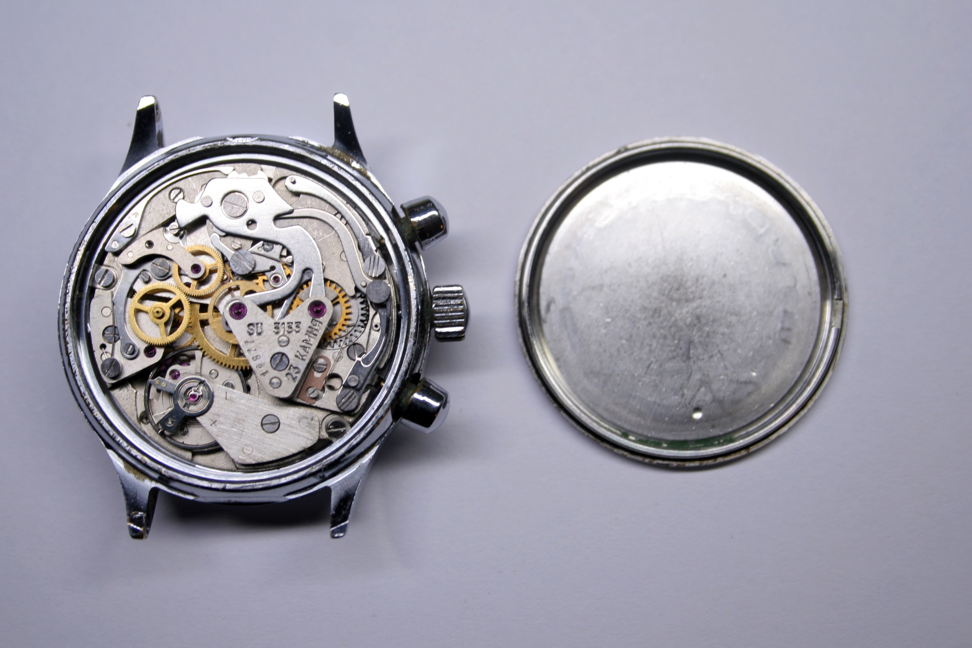
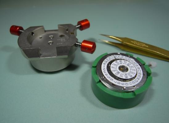
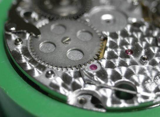
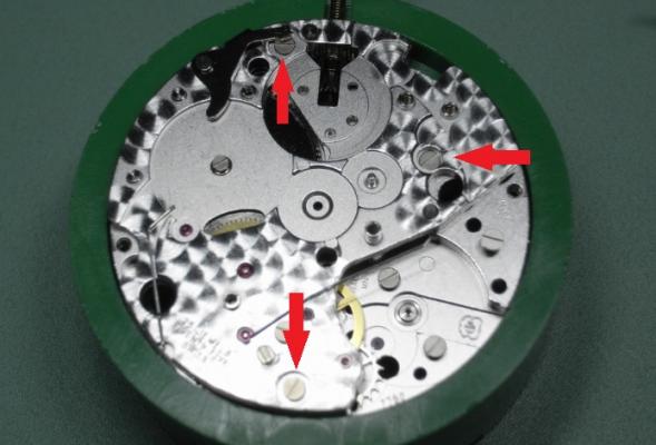
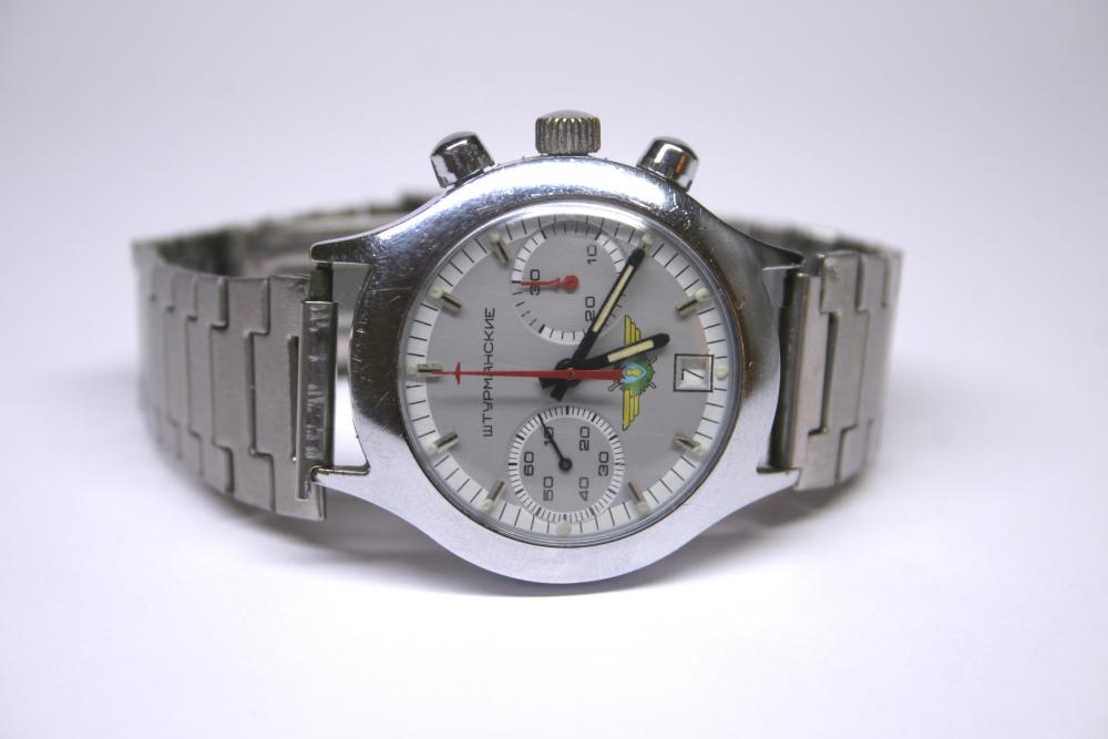
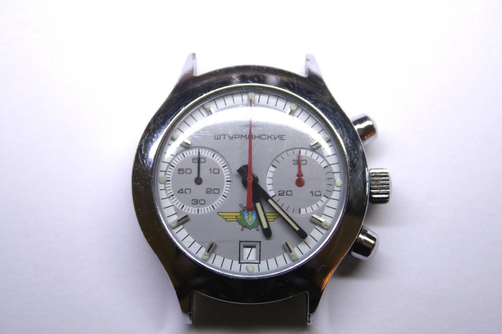
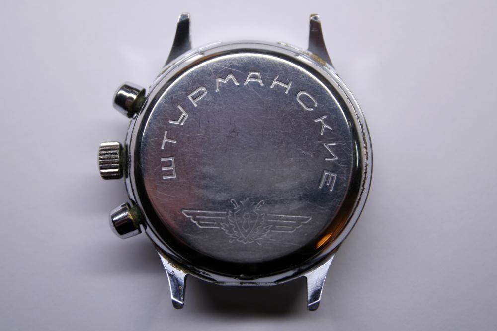
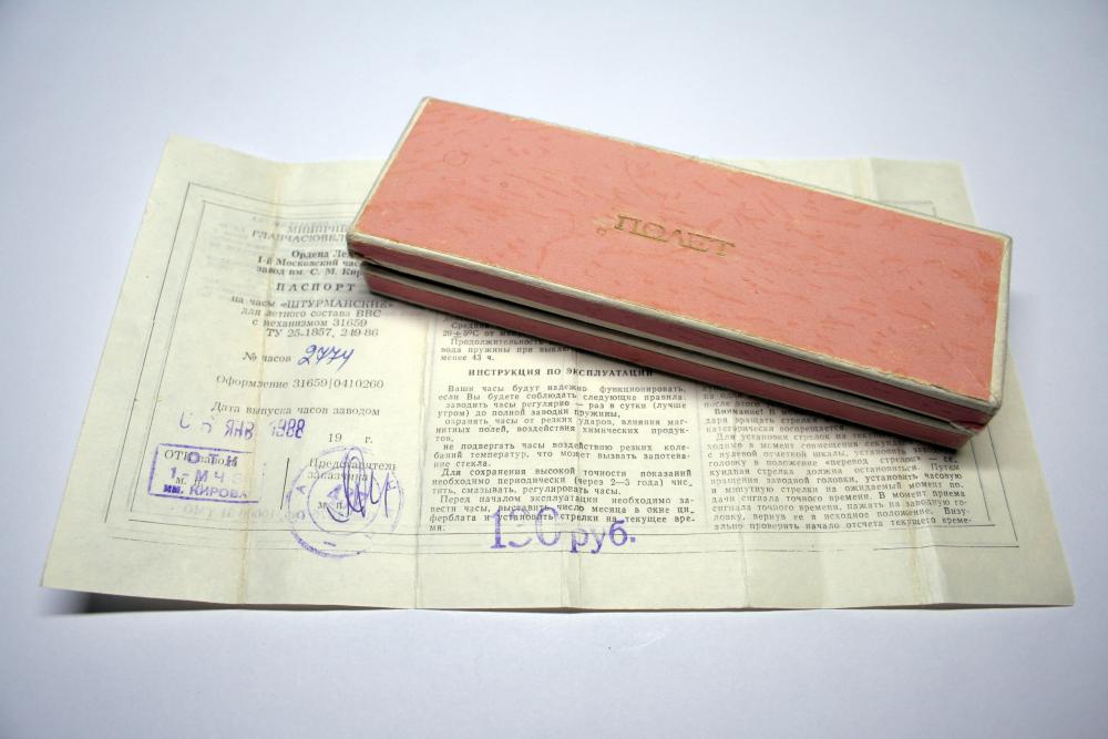
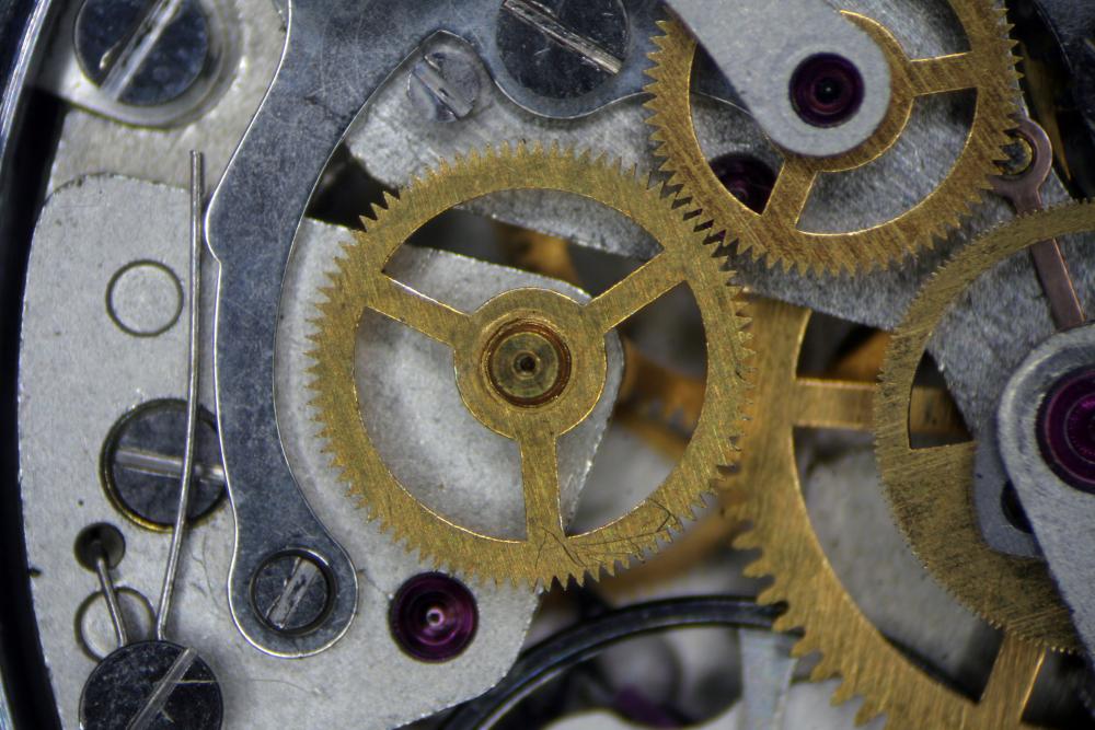
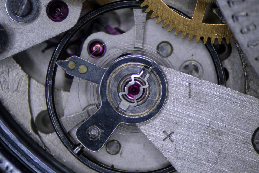
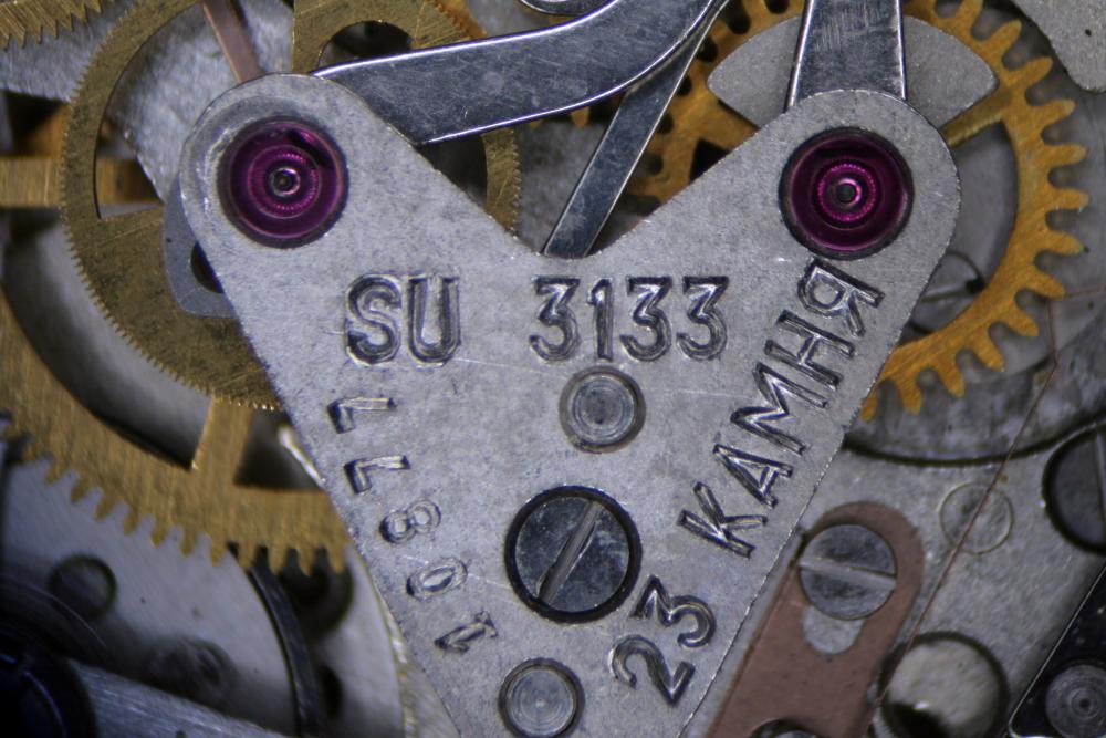
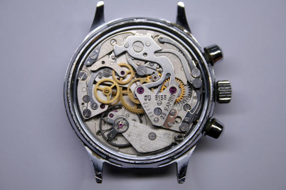
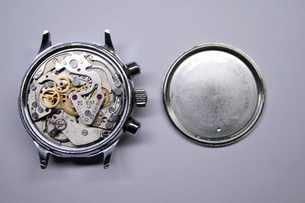
About a week back I picked up this Sturmanskie after following @Endeavor and @GeorgeClarkson through the service of their Soviet chronographs. The seller stated the watch dated from 1988 and included the original receipt and box. Unfortunately, I cannot read Cyrillic so I was forced to take the seller at his word; regardless of it's origin though, the watch is a beautiful specimen and I'm happy to have it. Unfortunately I was unable to remove the caseback until today. I took Roland's advice and used a jeweler's hammer and a sharp razor to work my way around the caseback slowly creating enough of a gap for a case knife to exploit. It was a nerve-wracking experience! In the end, the caseback came away with no damage to the watch. I'm always very anxious to gaze upon a new chronograph movement- it's certainly geeky but I'm not afraid to admit it. It looks like I'm not the first to open this case though. Many screws have marks on them indicating they've been removed at some point in the past and replaced. I believed this movement to be 31659, but alas, there is no hacking mechanism that I can see. Over all the movement is in good shape and appears complete. It will need a proper cleaning before it's ready to wear and I'll be sure to post about it when I have the chance.

 1 point
 -
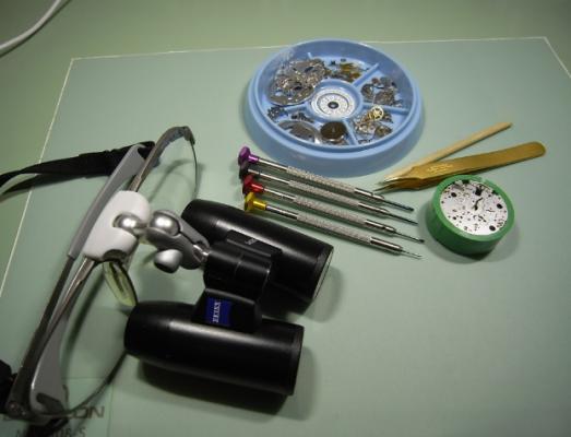
That could be another interesting thread, you photography setup! Or as a continuation on the existing " Horology Photography Thread"; http://www.watchrepairtalk.com/topic/3985-horology-photography-thread/#comment-40451 Very curious what your "good pictures" secrets are ..... Well, I'm not curious, I just want to know ....... !!1 point
-
Technician inspect the watch carefully, many parts to be changed, proposed full service. Accepted. Regarding the automatic device he told the pinions of the reverser wheel are damaged. Also told the beating of the rotor has to be replaced, one jewel is crooked, other parts worn out etc.1 point
-
for the case back, did you try this one? I bought one for a very stubborn case back and it worked.
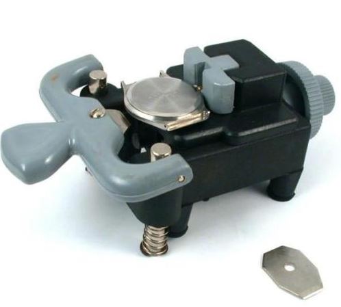 1 point
 -
Welcome Salvatore, The last line in your ad says it all....1 point
-
Worth a read..... just for the chuckle [emoji23] Welcome Sent from my iPhone using Tapatalk1 point