

-
Recently Browsing
- No registered users viewing this page.
-
Topics
-
-
Posts
-
 Have you got the pallet fork installed in the movement when you see the train move when using the setting works? As nevenbekriev said, without the pallet fork to lock the train, the behaviour you are describing is normal. If this is happening with the pallet fork installed, you have a problem in the gear train, it should be immobile when the pallet fork is locking the escape wheel. The fit of the circlip above the pinions on that wheel is crooked in your pictures, it should sit flat up against the upper pinion as in Marc’s picture. Hope that helps, Mark
 -
 Hi I got a Jaeger LeCoultre K911 movement, where one of the stems was broken. Part no. Should be 401. Im based in Europe and tried Cousins but its discontinued. They except to get stem in stock for cal. K916 but will that work? Or Is there a way out to join the ends?
 -
 The part was how it fell out of the movement - the train wheel bridge wasn’t screwed in. I’ll probably dismantle the part, if I can, to work it out. The train of wheels ran fine - it was only once the keyless works were installed I noticed the problem.
 -

By mthomas828 · Posted
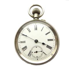
Hello, I am about 5 months into watchmaking and I love it! The attention to precise detail is what really attracts me to it. (and the tools!) I am working on a 16 jewel 43mm pocket watch movement. There are no markings besides a serial number (122248) . The balance staff needs replacement. The roller side pivot broke off. I successfully removed the hairspring using Bergeon 5430's. I successfully removed the roller using Bergeon 2810. Did i mention I love the tools?! I removed the staff from the balance wheel using a vintage K&D staff removal tool with my Bergeon 15285 (that's the one that comes with a micrometer adjustment so it can be used as a jewel press as well as a traditional staking tool...it's sooooo cool...sorry.. can you tell i love the tools?) No more digressing.. I measured the damaged staff in all the relevant areas but I have to estimate on some because one of the pivots is missing. A = Full length A= 4.80mm (that's without the one pivot...if you assume that the missing pivot is the same length as the other pivot (I'm sure it's not) then A = 5.12 mm...(can I assume 5.00mm here?) F= Hair spring collet seat F= .89mm (safe to assume .90 here? .. I am sure that my measurement's would at least contain .01 mm error ?) G = balance wheel seat G = 1.23 mm (1.20mm?) H = roller staff H = .59mm (.60 mm?) B = bottom of the wheel to roller pivot B = 2.97mm (3.00 mm?) here I am estimating again because this pivot is missing. So my friends, and I thank you profusely, can you point me in the right direction as to how to proceed? Do i buy individual staffs? or an assortment? Since I don't know exactly the name of the manufacturer, will that be a fatal hindrance? Tbh, I'm not even sure what country of origin this movement is. Thank you! -

By Neverenoughwatches · Posted
Thats why i asked that question earlier, what happens if lubrication is placed directly on top of epilame ? As opposed to walled within its non epilamed area . I'm not saying its right, i have no idea , just asking questions.
-


Recommended Posts
Join the conversation
You can post now and register later. If you have an account, sign in now to post with your account.
Note: Your post will require moderator approval before it will be visible.