Leaderboard


Popular Content
Showing content with the highest reputation on 07/28/18 in Posts
-
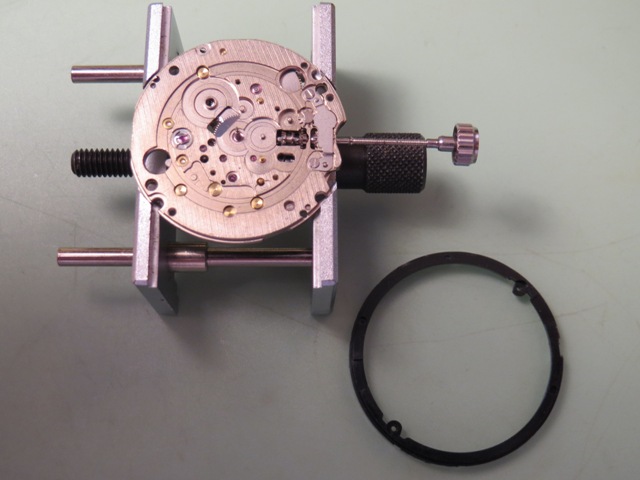
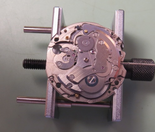
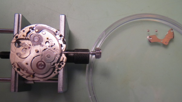
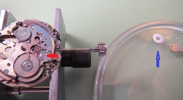
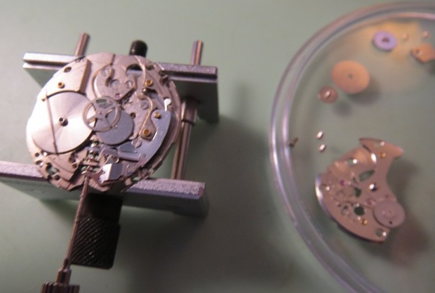
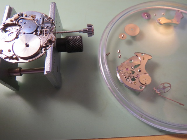
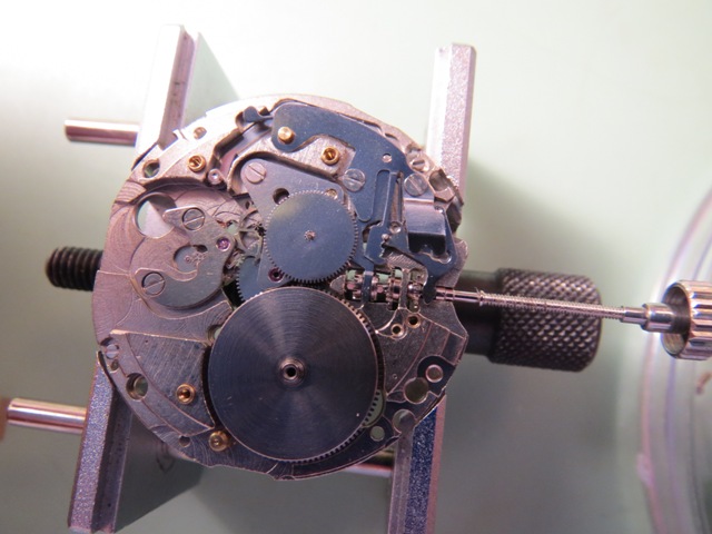
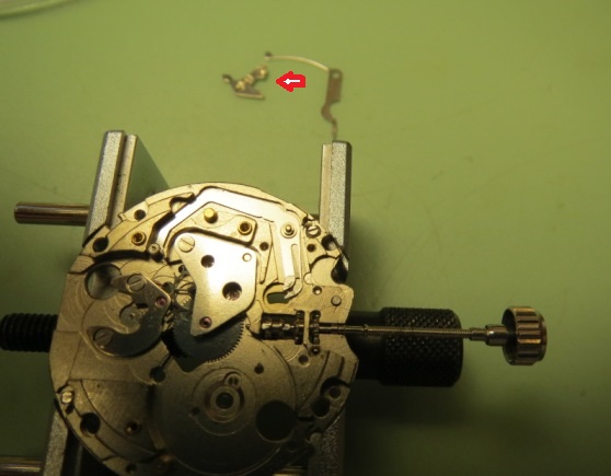
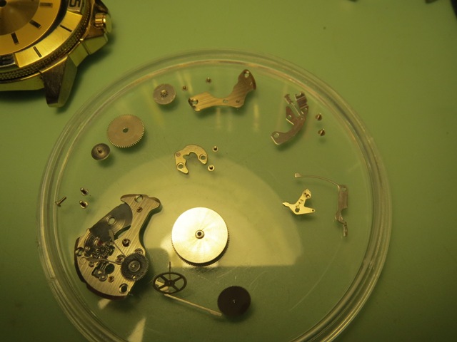
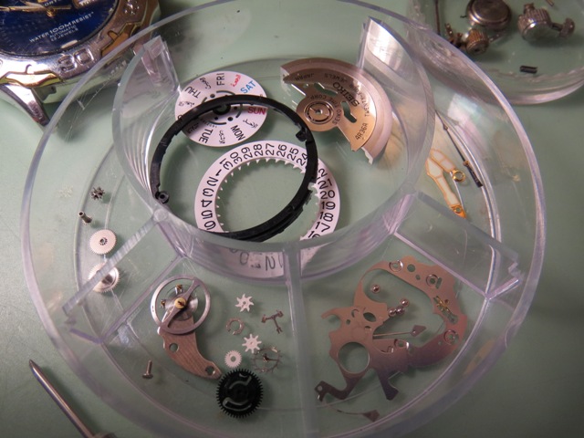
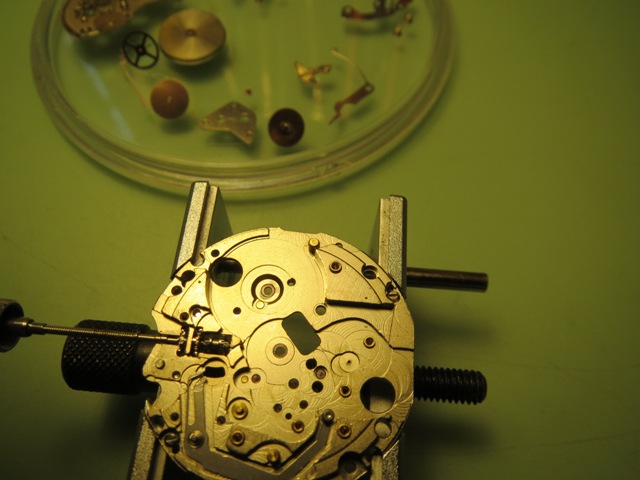
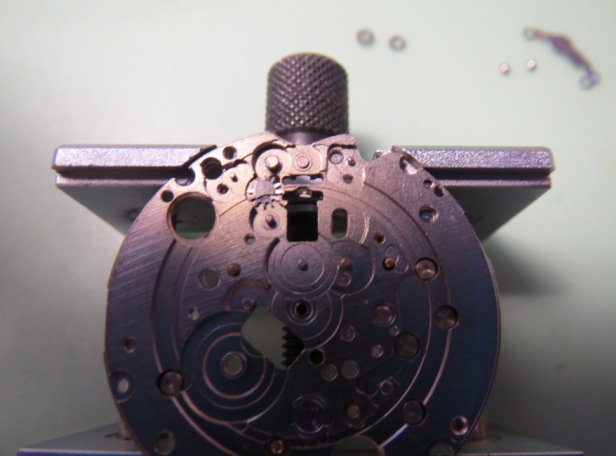
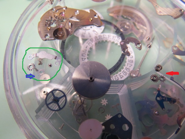
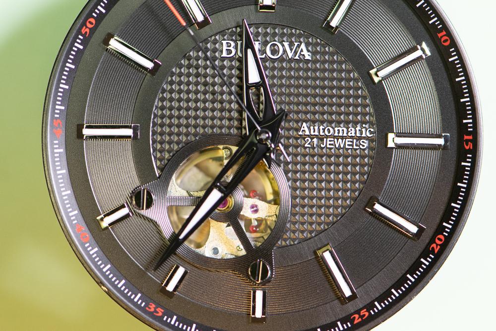
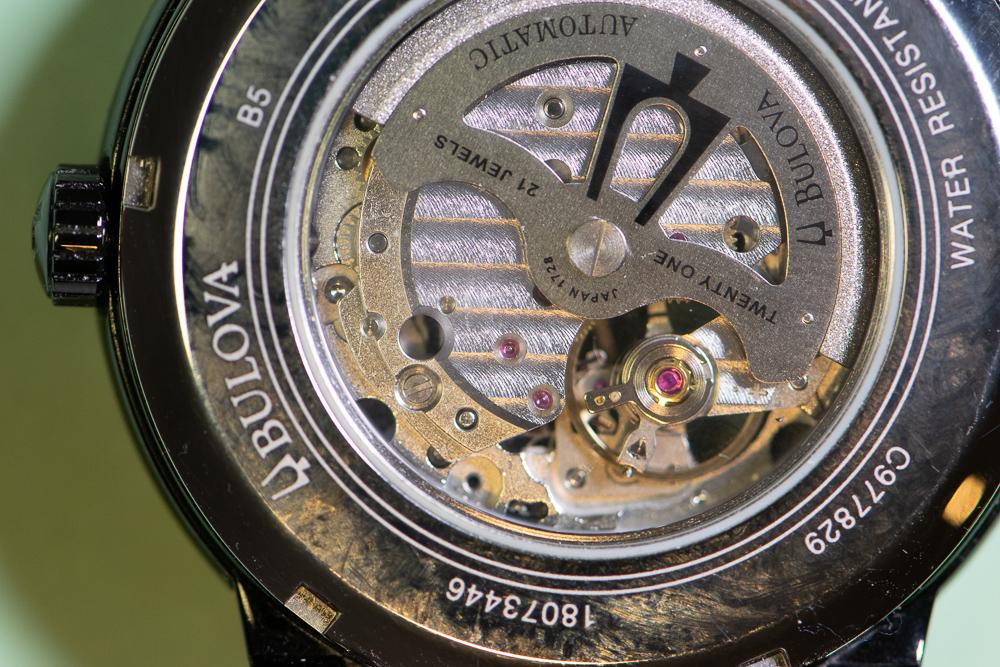
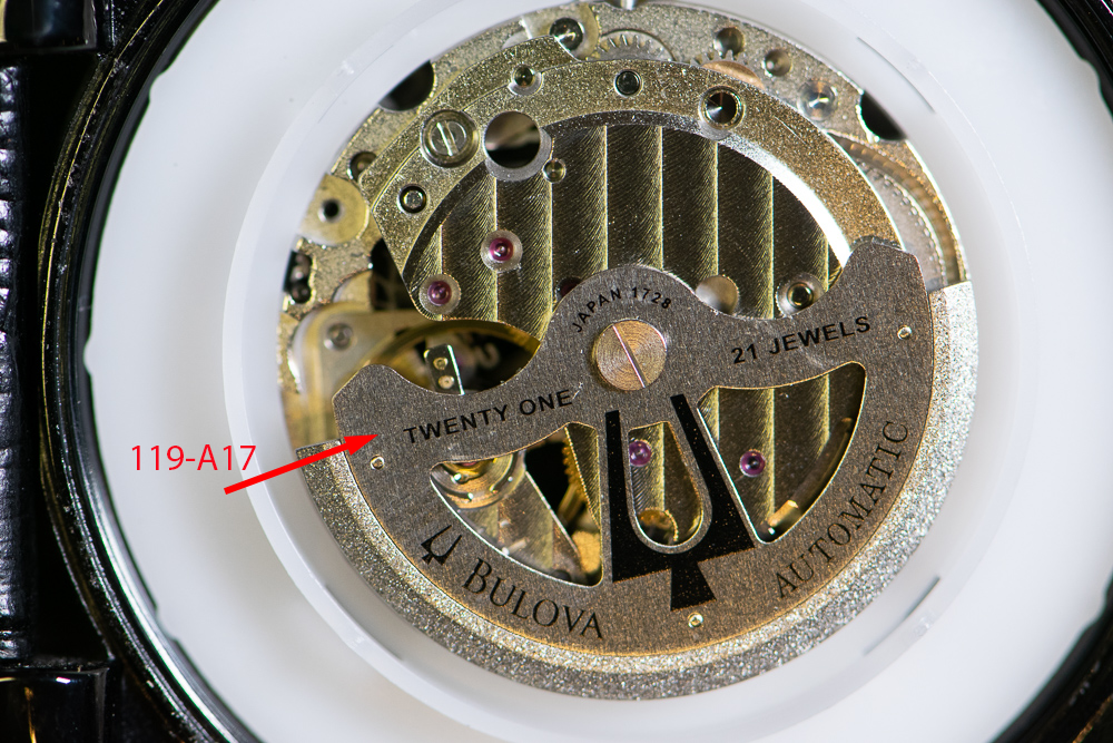
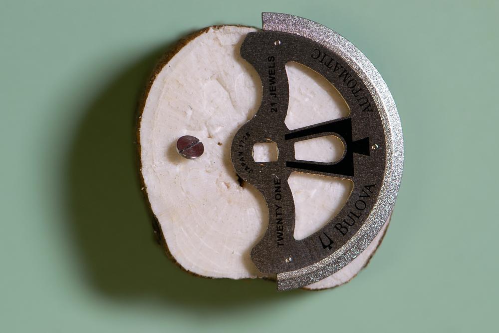
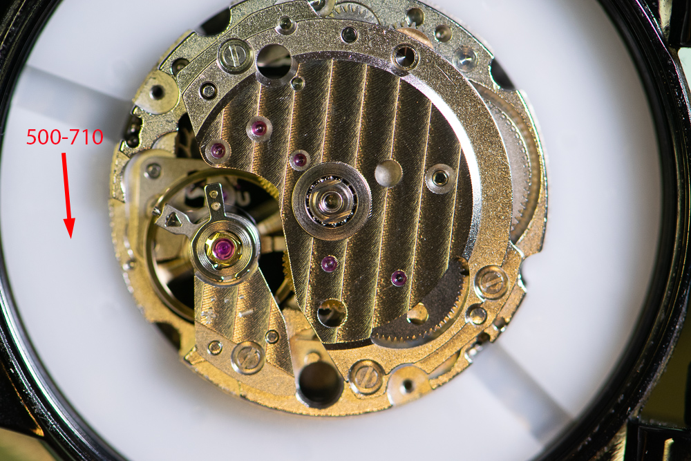
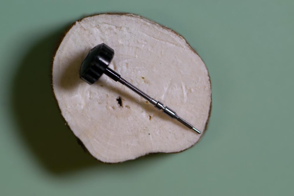
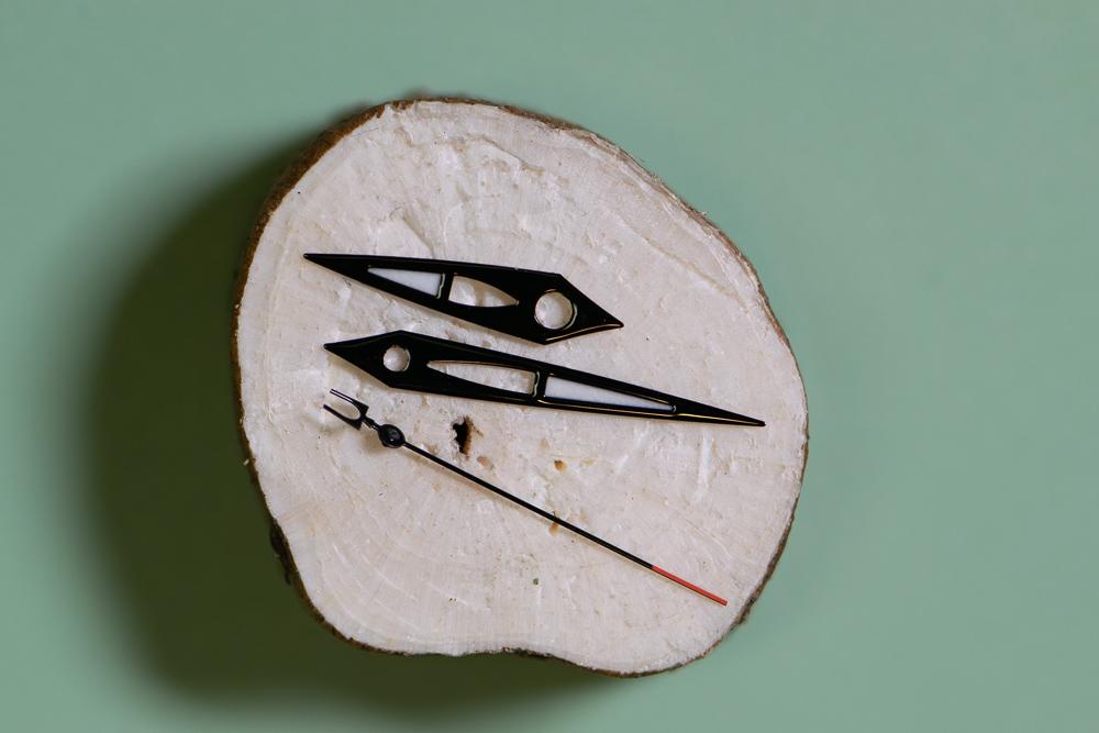
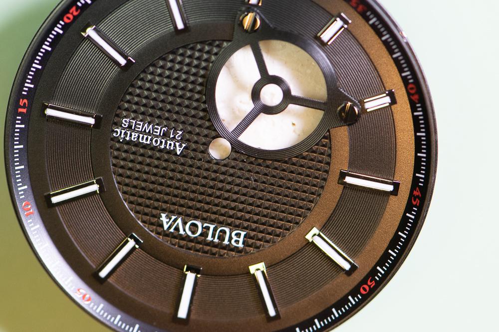
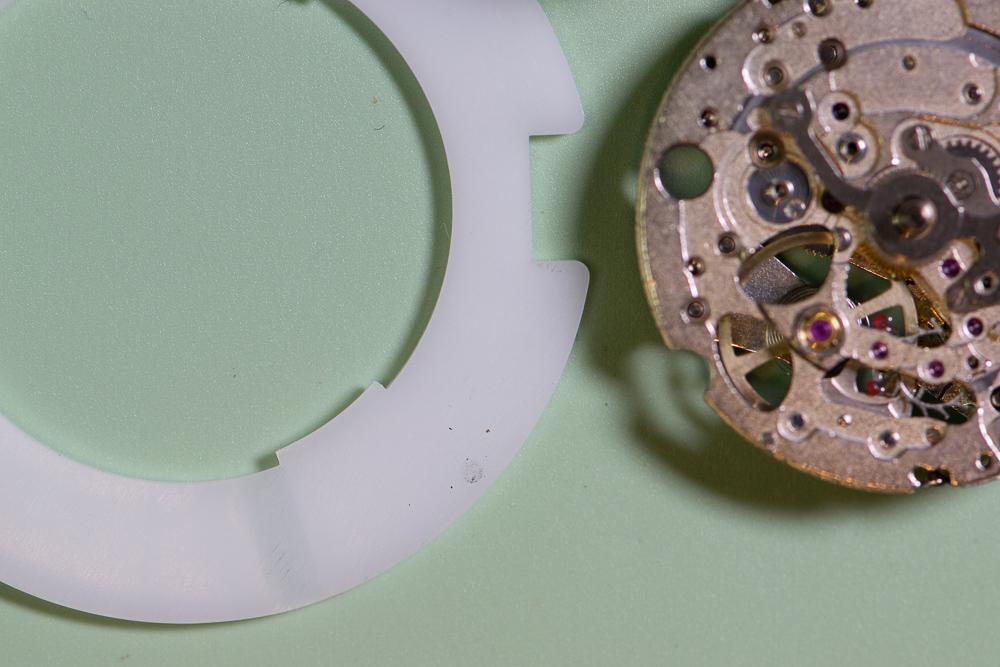
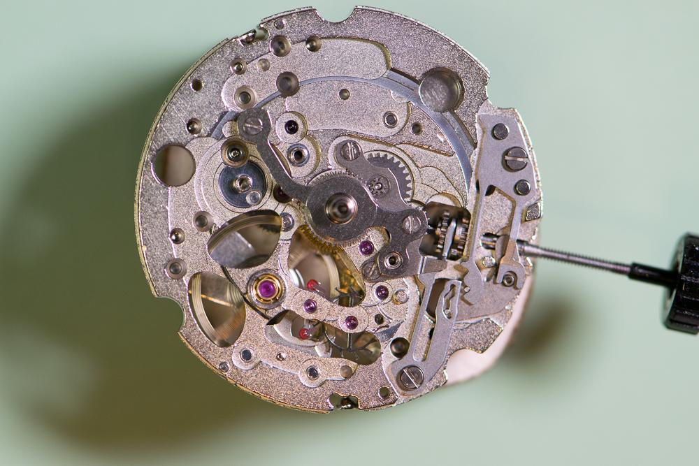
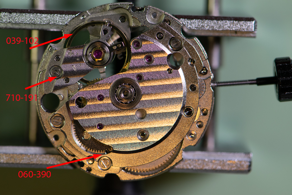
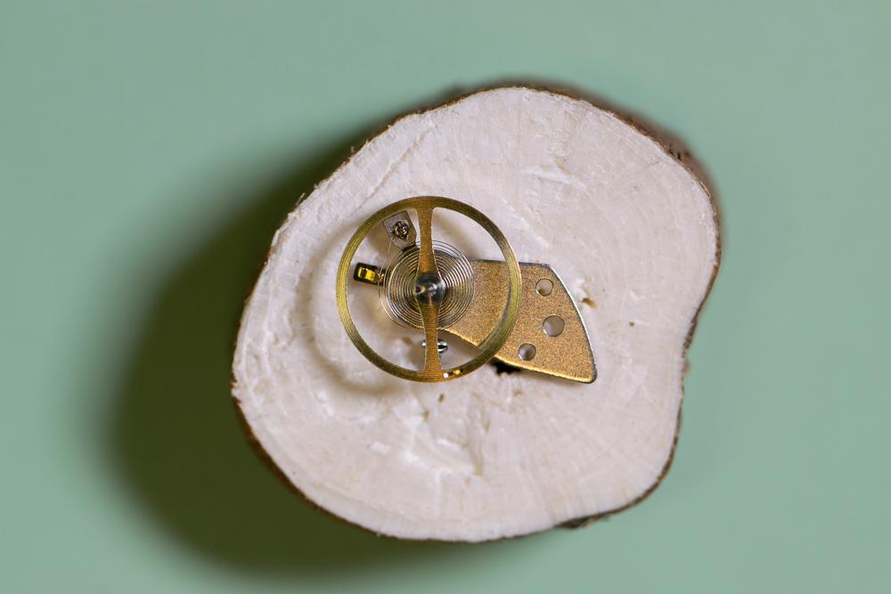
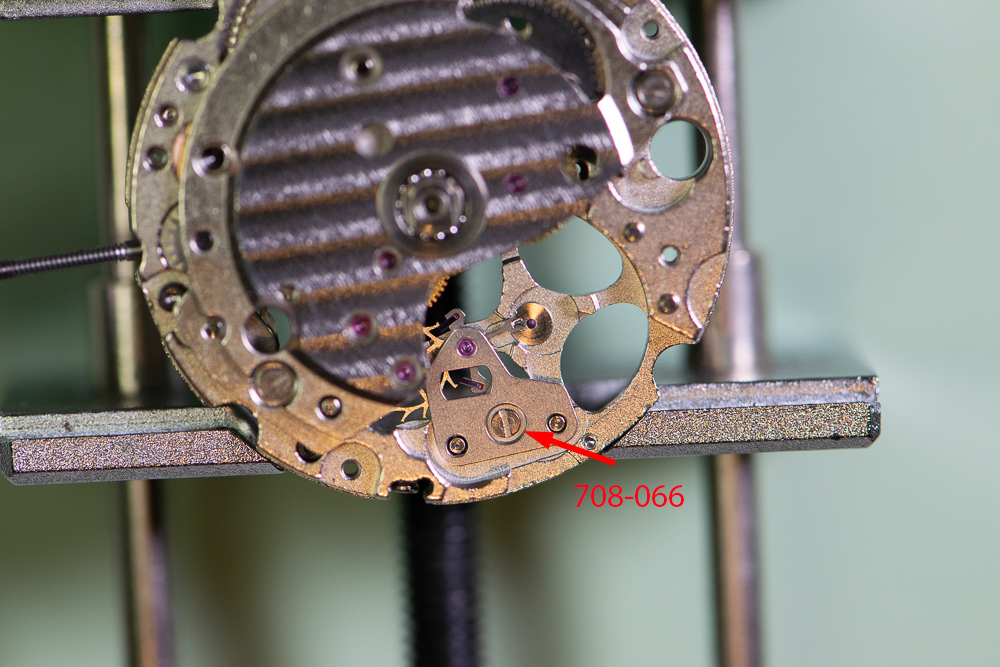
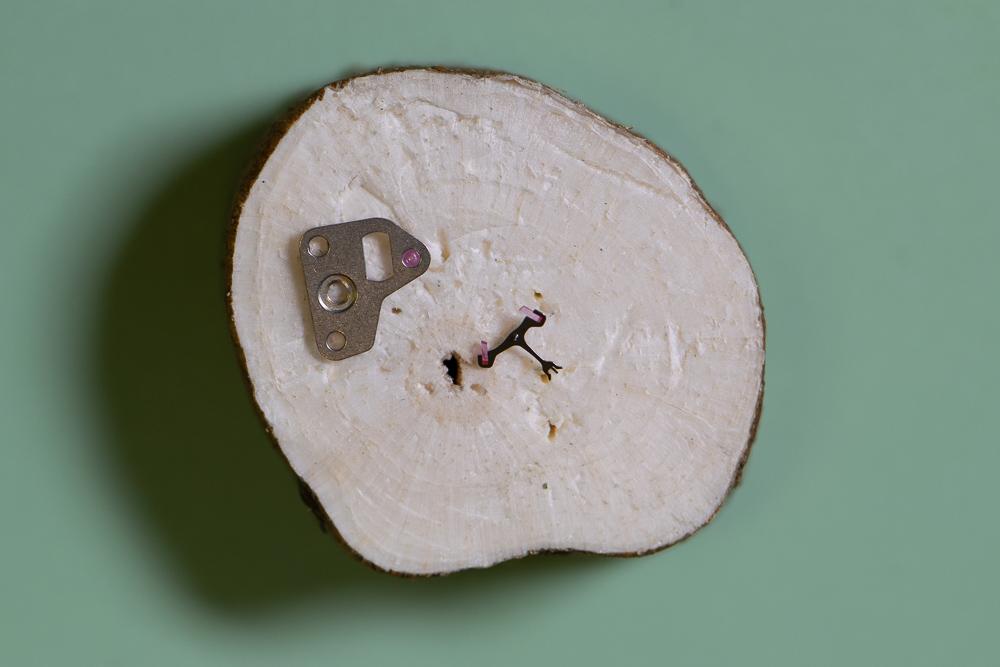
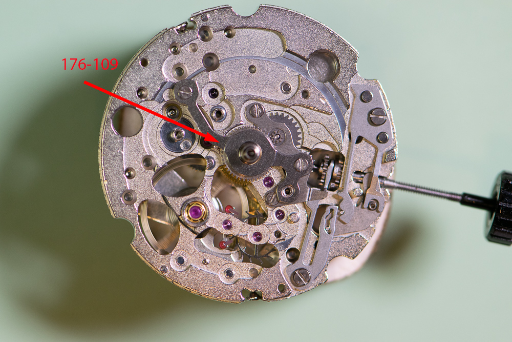
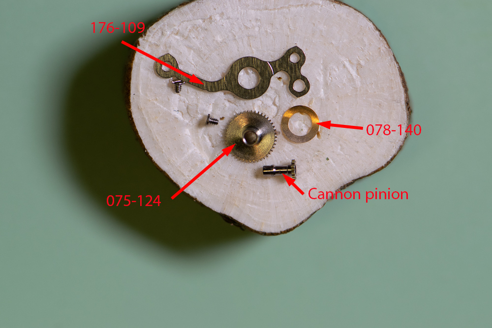
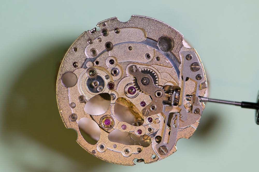
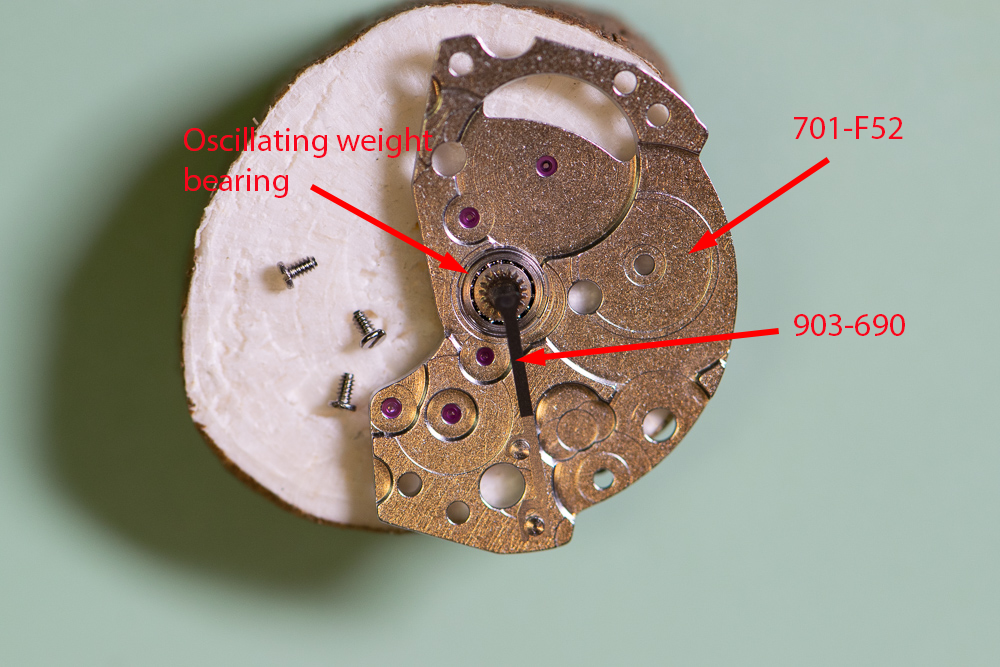
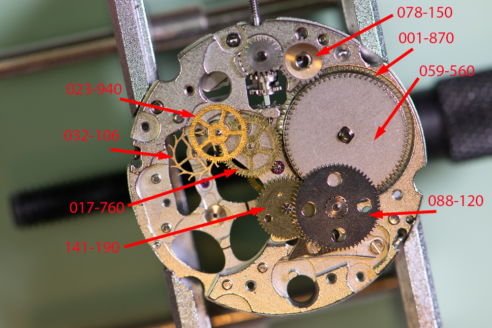
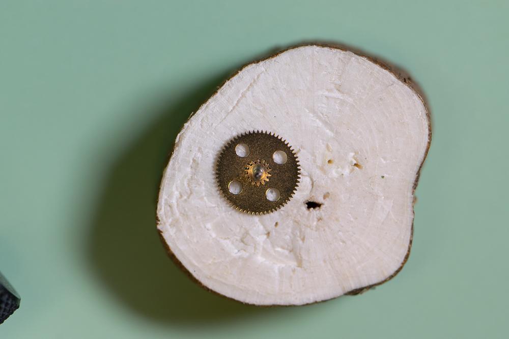
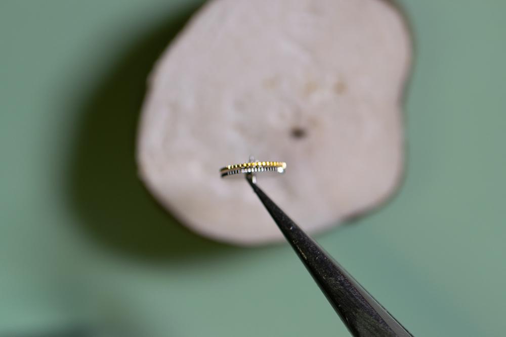
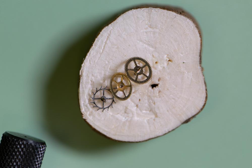
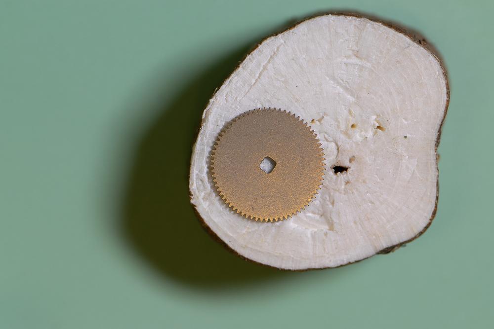
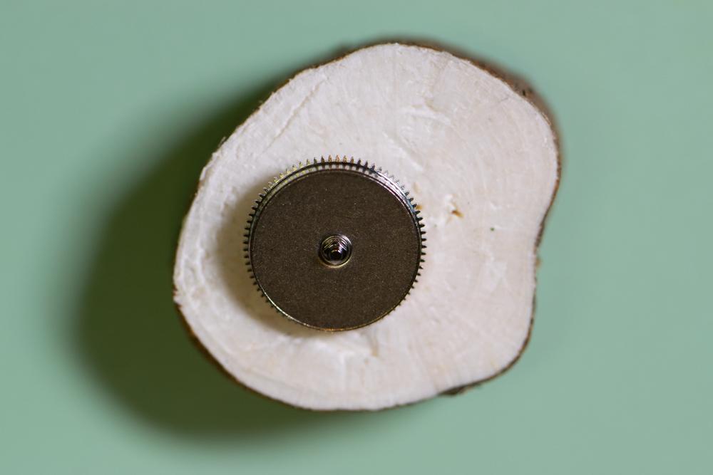
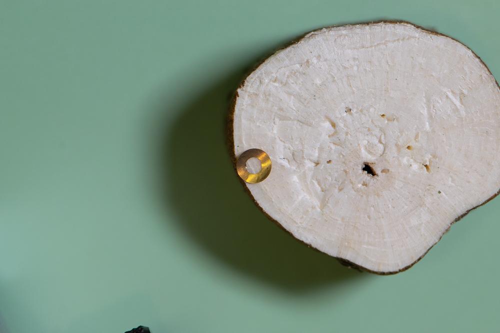
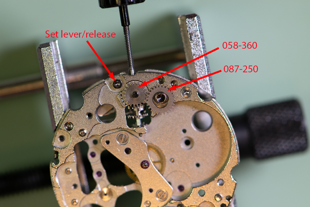
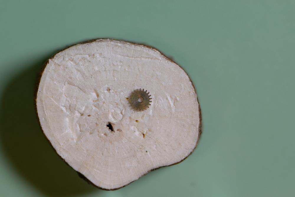
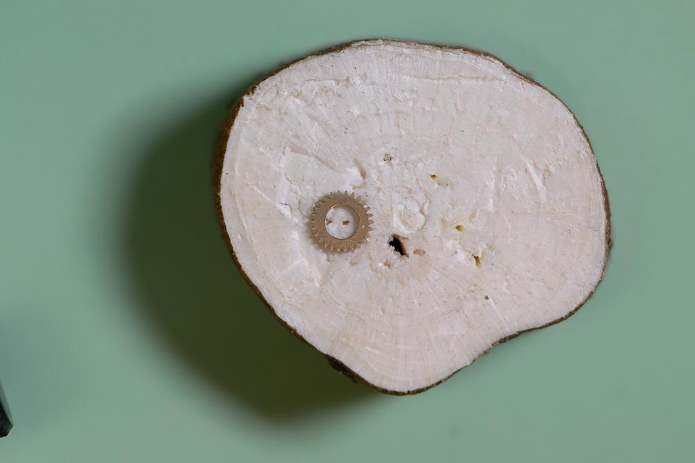
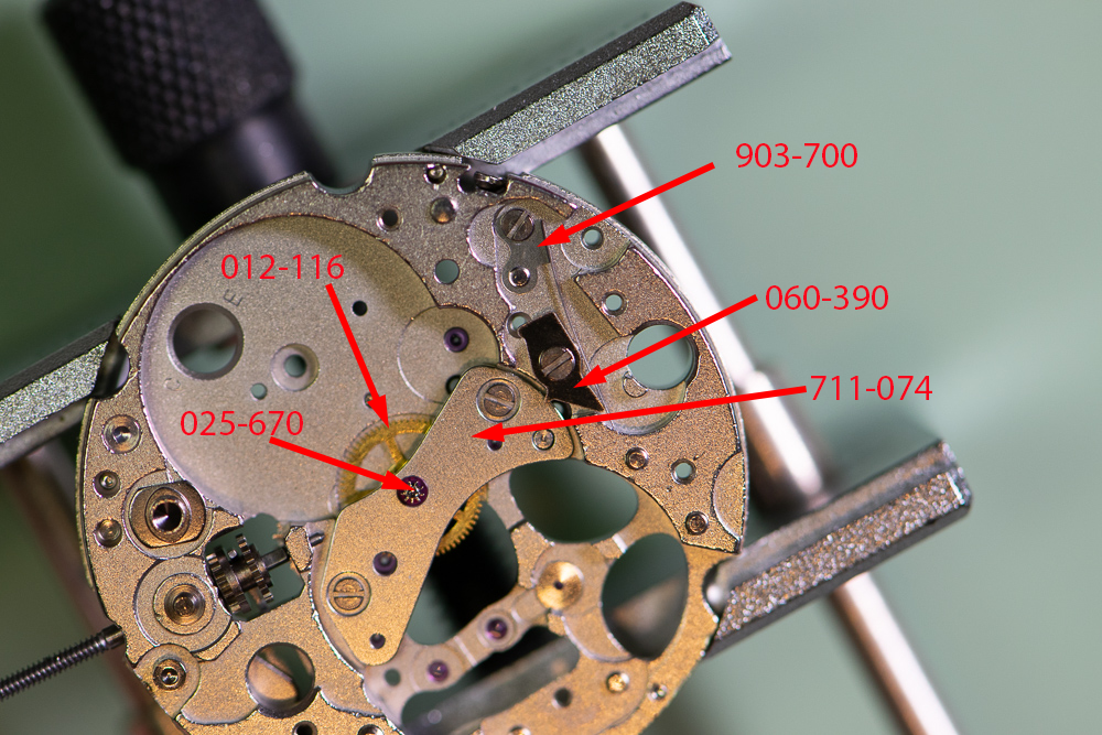
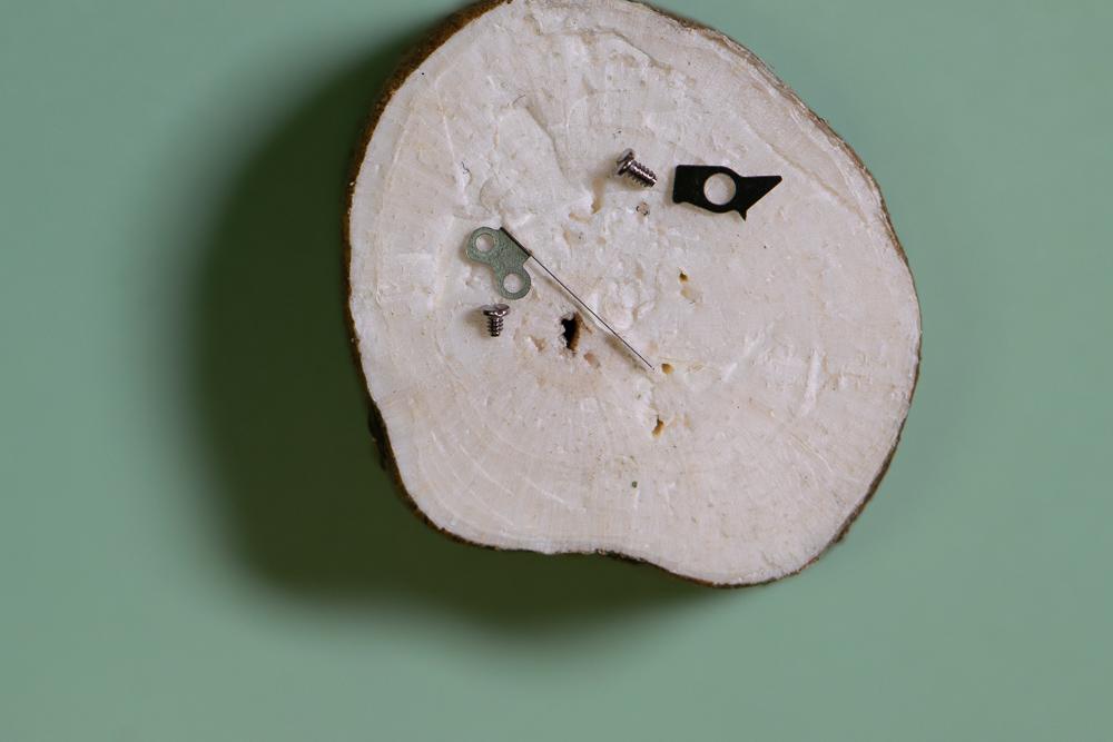
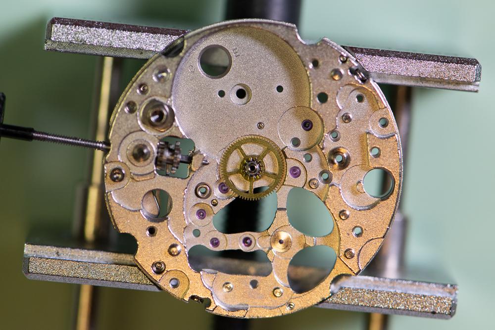
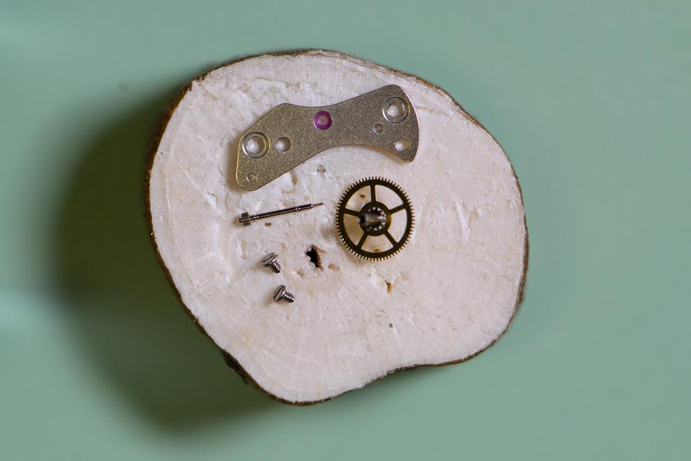
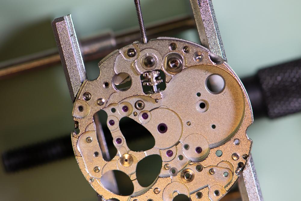
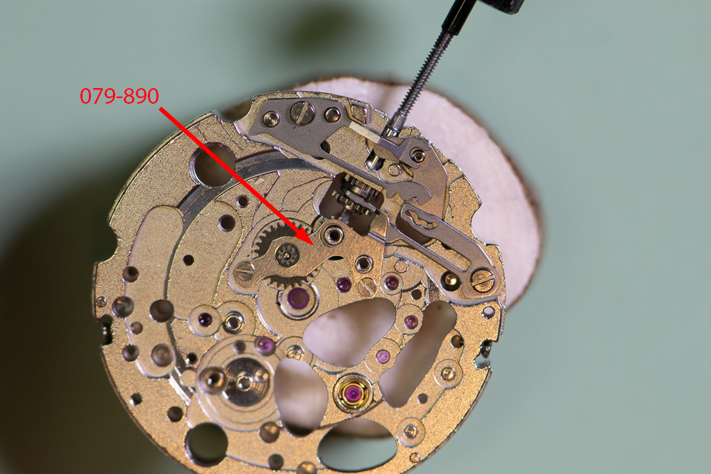
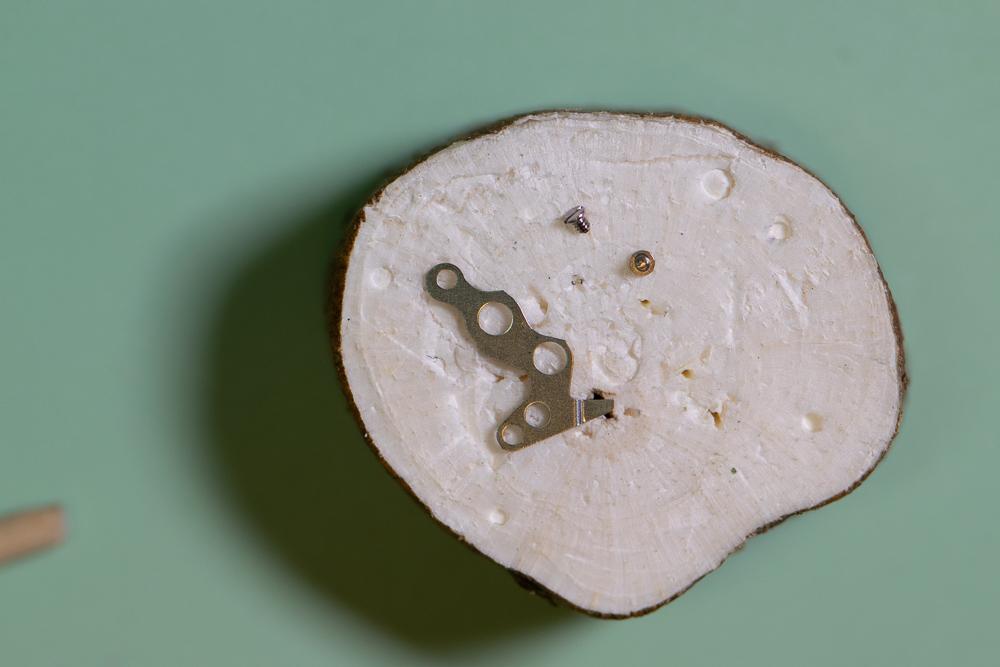
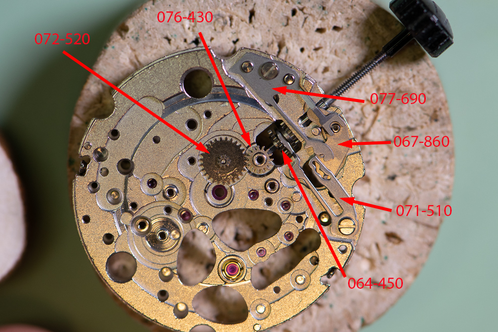
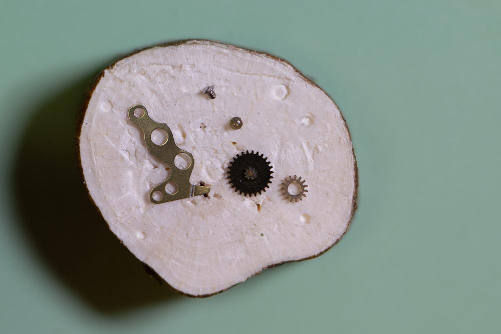
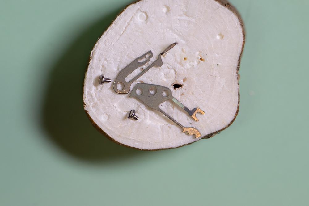
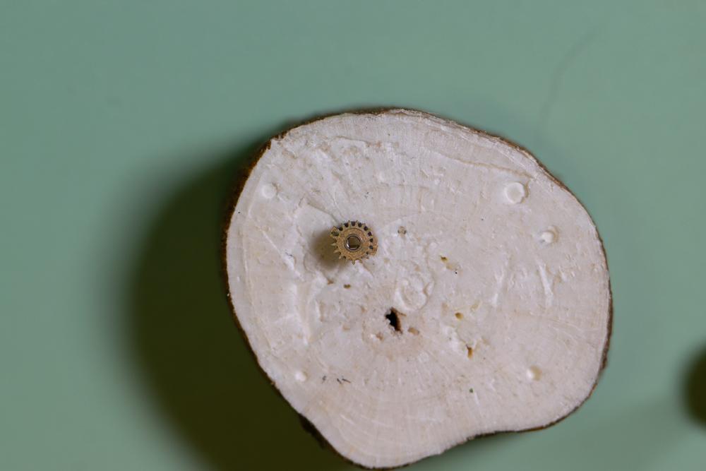
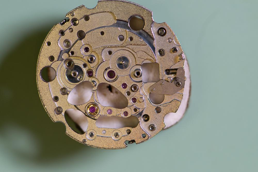
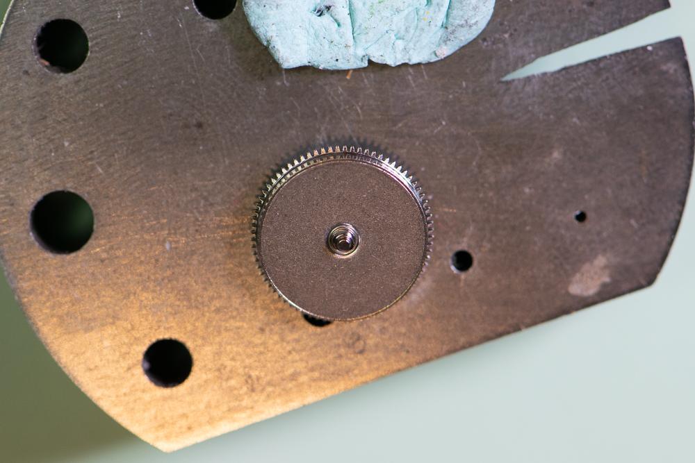
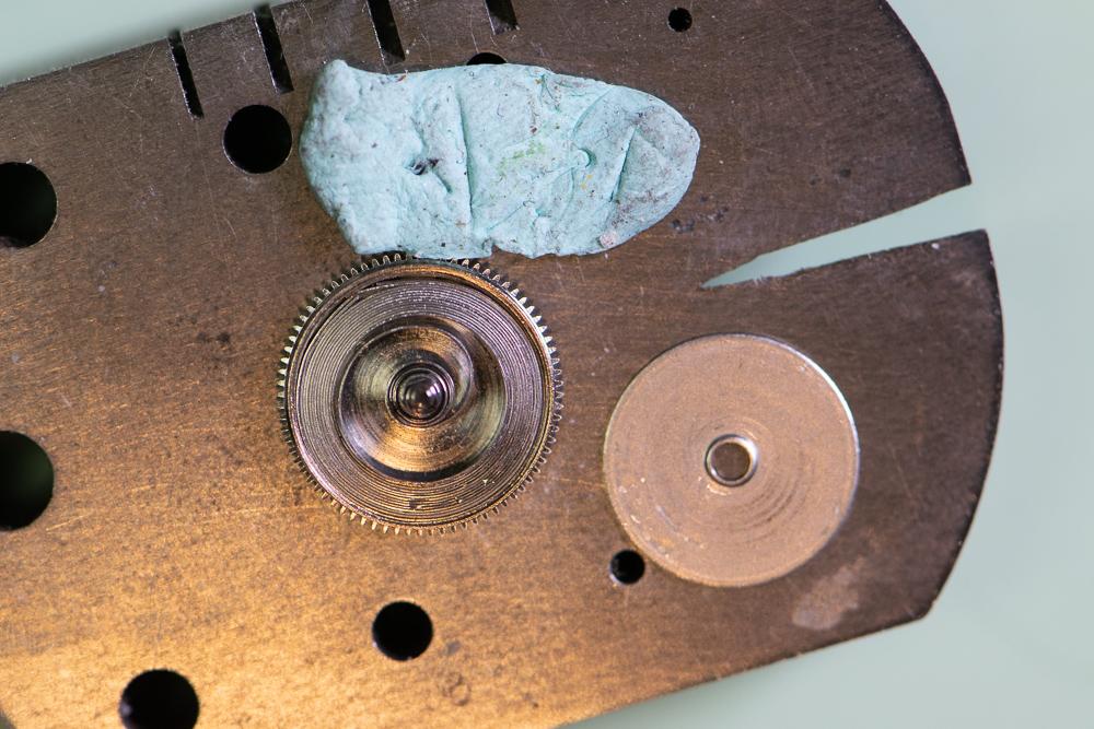
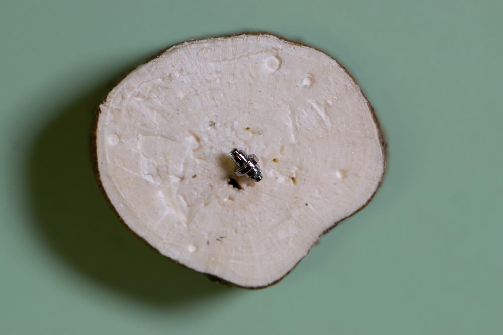
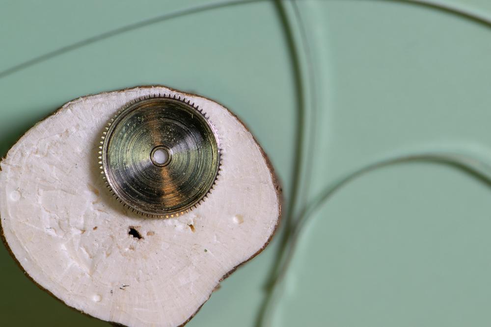
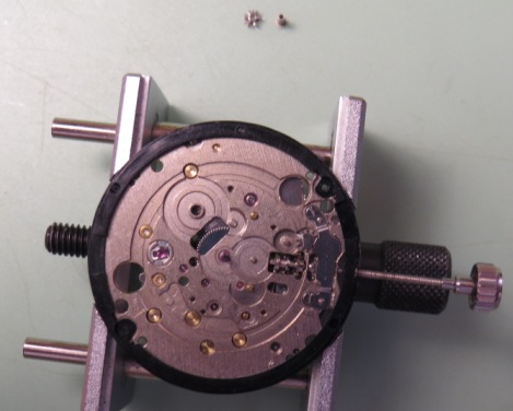
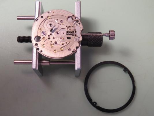
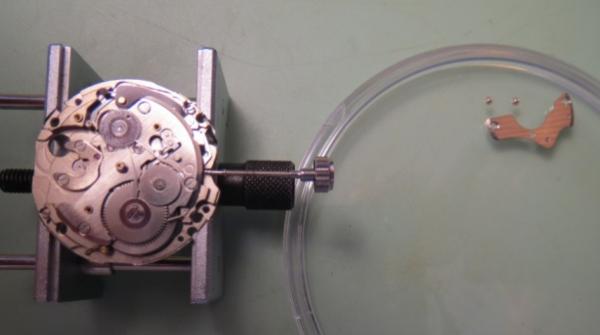
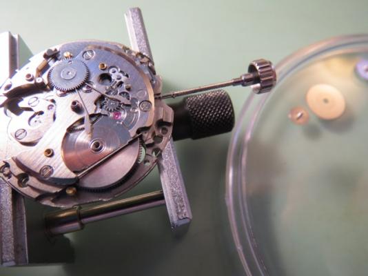
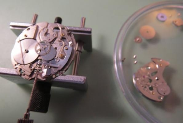
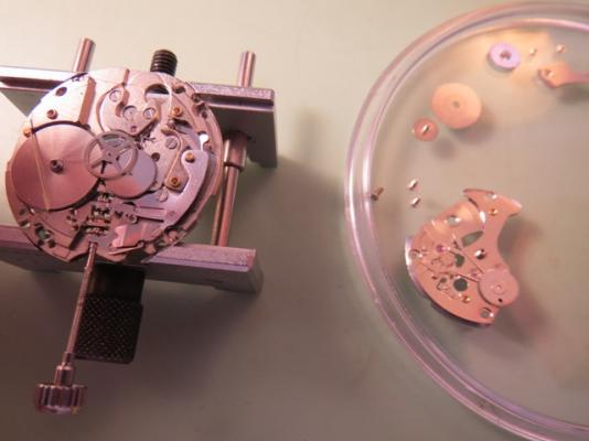
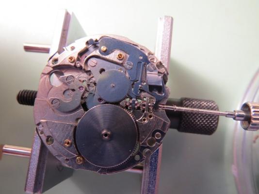
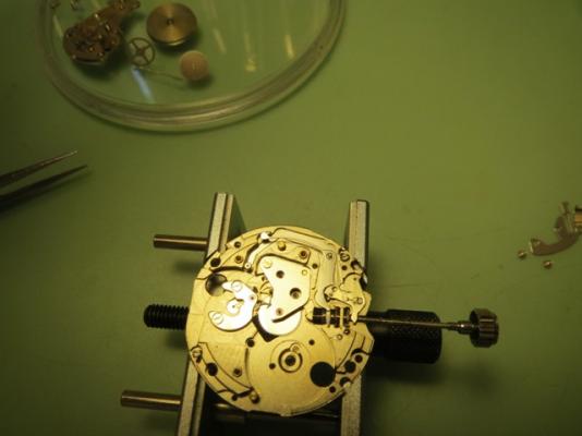
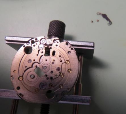
This is a more detailed version of my previous picture-only post for this watch. This Bulova 21-jewel automatic was given to me by a colleague for repair. It was running extremely fast – gaining about 15 minutes per hour. The movement is a Citizen/Miyota 82S0 skeleton. Looking through the clear back it was obvious that the balance amplitude was extremely low. First step was to simply demagnetize the watch to see if that did the trick as it sometimes does. No dice. I then removed the balance and pallets and put a small amount of wind onto the mainspring. The train spun up but as power wore off the escape wheel stopped, then started again several times. It was a very sloppy action. Nothing obvious in terms of loose or cracked jewels or excessive side or end shake that I could see. I decided to disassemble the movement and give it a full servicing. Here is how I disassembled the movement. Where I can I will list the Miyota part number for reference. You can find the parts list here: http://miyotamovement.com/parts_search.php?open=82S0 Figure 1 shows the face of the watch after removing from the case. Note the exposed balance at the 7 o’clock position. Figure 1 – Face Figure 2 shows the clear case back prior to removing the movement. Figure 2 – Case back The first step in disassembly is to remove the Oscillating weight (119-A17. Note that the weight is secured to a bearing that is pressed into the main plate. Unlike many Swiss movements, the screw securing the weight rotates with the weight itself. I used a peg wood stick to prevent the weight from rotating while unscrewing the fastener. Figure 3 shows the weight prior to removal. Figure 4 shows the oscillating weight after removal. Figure 3 – Preparing to remove the oscillating weight Figure 4 – Oscillating weight Figure 5 shows the movement after removing the oscillating weight. The plastic movement holder (500-710) is also visible. This will be removed after dealing with the hands and dial. I also removed the winding stem (figure 6) by pressing in on the setting lever and gently pulling the stem. The location for pressing on the setting lever was clipped from the pic, but it’s a standard setup. Figure 5 – Plastic movement holder Figure 6 – Winding stem After removing the stem, the movement was removed from the case. The stem was then reinstalled to facilitate power let-down, etc. With the oscillating weight removed, it’s a simple matter to lay the movement down dial-up on a piece of pith wood and remove the hands (Figure 7). The dial retaining screws on the side of the movement are loosened (not removed) and the dial is gently coaxed away from the movement by inserting a thin screwdriver blade. Figure 8 shows the dial after removal. Figure 7 – Hands Figure 8 – The Dial The movement holder shown in figure 5 is now lifted off. It is shown in figure 9 next to the movement. Figure 9 – Movement holder ring Figure 10 shows the dial side of the movement. Figure 10 – Dial side The movement is then flipped dial down and loaded into a movement holder for disassembly. The balance (039-102) is removed along with the balance bridge (710-191) as shown in figure 11. Figure 11 – Preparing to remove balance The balance complete is shown after removal in figure 12. Figure 12 – The balance complete Important: Before removing the pallets I need to remove all the power from the mainspring. I do this in the standard way – by applying a bit of winding pressure on the crown while pulling the click (060-390 in figure 11) out of the way with a bit of peg wood and allowing the stem to unwind in a slow/controlled manner. Figure 13 – About to remove pallets With the power let down I can now remove the pallet bridge (708-066) and pallets. Figure 13 shows the bridge prior to removal. The pallets and bridge are shown in figure 14. Figure 14 – Pallets and pallet bridge I probably should have removed the motion work prior to starting in on the balance – not sure why I didn’t. Regardless, we need to flip the movement back so I can remove the motion work from the dial side. The hour wheel is held in place by the hour wheel spring (176-109). Remove the 2 retaining screws and then lift off the spring. The spring is shown prior to removal in figure 15. Figure 15 – Hour wheel spring prior to removal Once the hour wheel spring is out of the way I can remove the dial washer (078-140), the hour wheel (075-124) and finally the cannon pinion (using your favorite cannon pinion removal tool). These parts are shown after removal in figure 16. Figure 16 – Hour wheel spring, hour wheel, dial washer and cannon pinion Figure 17 shows the movement after removal of the motion work. It’s now time to flip the movement back over and start in on the gear train. Figure 17 – After removing the motion work I remove the three screws securing the barrel and train wheel bridge (701-F52) and carefully remove it. Figure 18 shows the underside of the bridge. Note that the seconds pinion friction spring (903-690) was left in place. I didn’t see the point in removing it. You can also see the oscillating weight bearing that is press fit into the bridge. I didn’t mess with this either! Figure 18 – Barrel and train wheel bridge and seconds pinion friction spring Figure 19 shows the detail after removing the barrel and train wheel bridge. First, I remove the reduction gear (088-120) and reversing wheel (141-190). These components are part of the automatic winding mechanism. They are shown in figures 20 and 21 after removal. I make note that the reversing wheel should be installed with the brass side up. Figure 19 – After removing barrel and train wheel bridge Figure 20 – Reduction gear Figure 21 – Reversing wheel Next, remove the third wheel (017-760), fourth wheel (023-940) and escape wheel (032-106). These are shown in figure 22. Figure 22 – From left to right – escape wheel, fourth wheel and third wheel Next, I remove the ratchet wheel (059-560) and the barrel complete (001-870), which sits directly underneath the ratchet wheel. Th.ese components are shown in figures 23 and 24. Figure 23 – Ratchet wheel Figure 24 – Barrel complete Looking back at figure 19, you can see a spring, very similar to a dial washer. This part is called the ratchet sliding wheel spring (078-150). Simply lift it off (figure 25). Figure 25 – Ratchet sliding wheel spring With the spring out of the way I can now see the ratchet sliding wheel (087-250). I remove this part along with the crown wheel (058-360). Figure 26 shows these parts. Ah – finally a picture that shows the setting lever release button I mentioned earlier! Pressing here allows the stem to be removed. I will leave the stem in place for now. Will get to it shortly. Figures 27 and 28 show the parts just removed. Figure 26 – Crown wheel and ratchet sliding wheel Figure 27 – Crown wheel Figure 28 – Ratchet sliding wheel Figure 29 shows the click (060-390) and click spring (903-700), the center wheel cock (711-074), center wheel (012-116) and center seconds pinion (025-670). Technically I believe the center wheel cock should be named the center wheel bridge since it’s secured by more than one screw, but I’ll leave that open for debate. Tension on the center seconds pinion is provided by the friction spring we saw back in figure 18. Figure 29 – Click and spring, center wheel and cock, center seconds pinion Figure 30 depicts the click and click spring after removal. Figure 30 – Click and click spring Figure 31 shows the center wheel in place after the center wheel cock has been removed. Figure 31 – After removal of the center wheel cock Figure 32 depicts these parts after removal. Figure 32 – Center wheel cock, center wheel and center seconds pinion The train side of the movement is now fully stripped. This is shown nicely in figure 33. Time to flip it over and finish off the dial side. Figure 33 – Finished with the train side Figure 34 shows the current state of the dial side of the movement. To get started I remove the minute train cover (079-890). Figure 35 shows this component after removal. Figure 34 – Dial side Figure 35 – Minute train cover I can now remove the keyless work. The components are shown in figure 36. The minute wheel (072-520) and setting wheel (076-430) are removed first. These components are shown in figure 37 along with the minute train cover. Figure 36 – Keyless work components Figure 37 – Minute and setting wheel Referring back to figure 36, the next components to remove are the yoke (071-510) and setting lever spring (077-690). The stem can now be removed and then the clutch (064-450) is free to remove. The setting lever (067-860) was not removed as it’s press button is staked (spread). No sense disturbing this. Figure 38 shows the yoke and setting lever spring after removal. The clutch is shown in figure 39. Figure 38 – Yoke (left) and setting lever spring Figure 39 - Clutch Finally, the main plate is fully stripped. The dial side is shown in figure 40. Figure 40 – Main plate – dial side We can now deal with the barrel assembly (figure 41). Figure 41 – Mainspring barrel complete Using the steel anvil for support, gently press down on the gear teeth to pop the barrel cover off (figure 42). Figure 42 – Barrel cover removed Carefully remove the barrel arbor (figure 43). Figure 43 – Barrel arbor Unwind the mainspring from the barrel (figure 44). Figure 44 – Barrel with spring removed This completes the disassembly of the movement. My next step will be to clean it in the ultrasonic. Will post the reassembly as a new thread.
 1 point
 -
Ok thanks. I really like the watch. May have to take it to a watch place.
 1 point
 -
Yes, the dial davalues this watch significantly. They are nice movements top work on, like the 30T2, so I don't think it's so bad to be working on it. Just don't break any pivots! Watch Mark's videos on youtube showing basic servicing. The cost of a new balance complete makes this project probably not great value. Getting a spares movement isn't such a great option as since the watch has no anti-shock, the balance staff is much more likely to be broken. I'd sell it and buy another if I were you.1 point
-
You used the right word. If you photographic forums, people often use it to refer to their piece in comparison to a standard quality level..1 point
-
Well in this case quality becomes relative considering the poorly repainted dial.1 point
-
Most of us here do this for fun. A timegrapher is an essential tool, fortunately it's not expensive neither in physical or application form, much cheaper than a vintage cleaning machine, but much more useful. Not knowing your experience and skills I suggested that you bring it to a competent person to avoid the possibility of ruining something that seems you care for. Of course if you know how to work on a movement yourself that's even better. I also love working on cars and motorbikes (was a professional when younger) but found that watch work is much more difficult than anything else, at least under the manual dexterity aspect.1 point
-
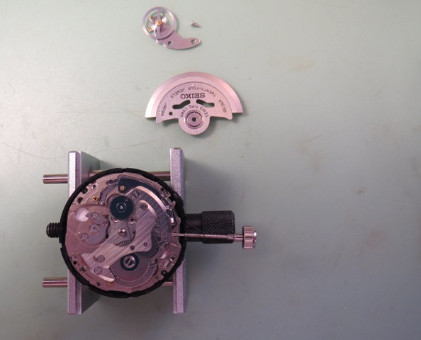
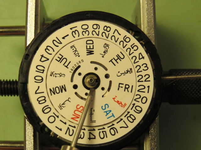
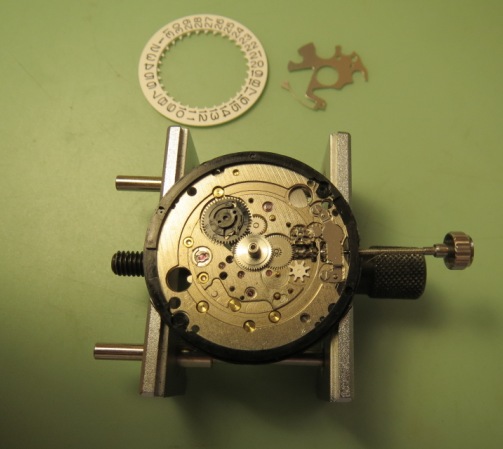
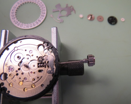
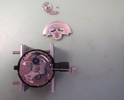
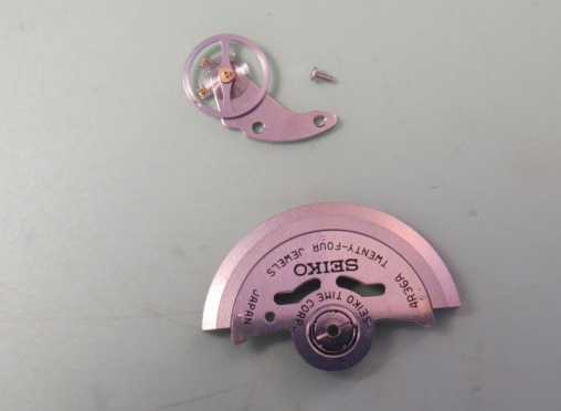
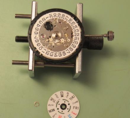
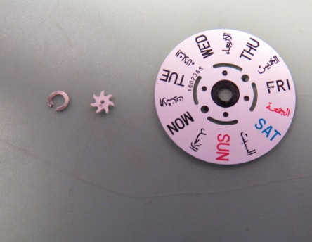
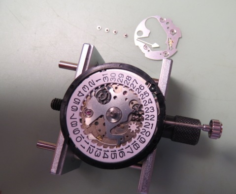
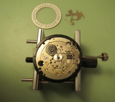
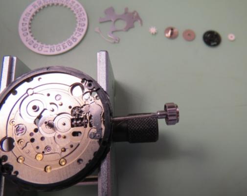
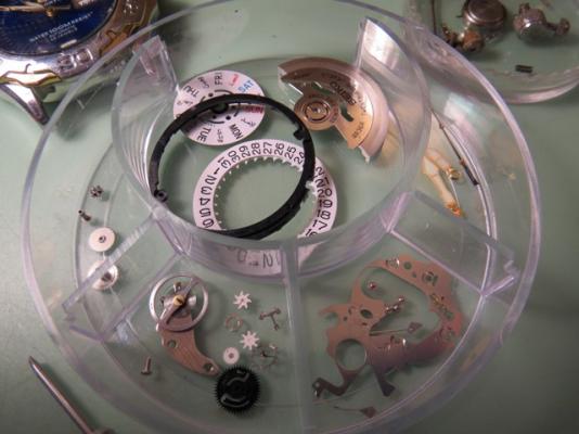
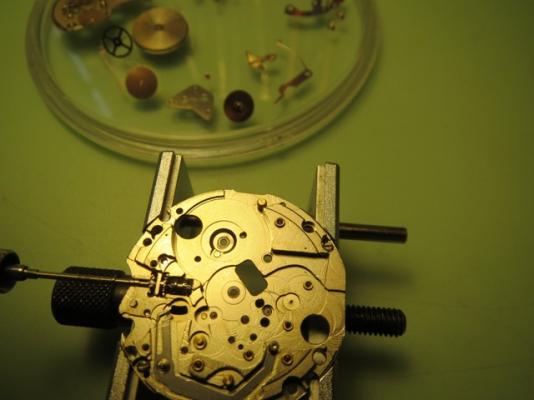
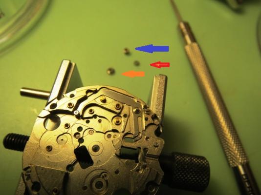
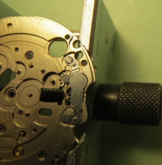
Seiko NH36 Walkthrough This walkthrough complements the 7S26/7S36 excellent walkthrough on this site by Lawson (http://www.watchrepairtalk.com/topic/682-seiko-7s26a-complete-service-walkthrough/). I strongly recommend to check out Lawson's walkthrough first). This is a more recent movement based on the said 7S26. It is a 24 jewels day/date, center seconds, movement with hacking capabilities and manual wind. The ligne is like its predecessors ~12. It is popular in the new Seiko models and Invicta watches among others. In brief, former movements didn't have hack or manual wind. Still, several parts are interchangeable with the older 7Sxx series. Here is the service data: 6810_Seiko NH3 Series Part Sheet.pdf My first step here will be to remove the "oscillating weight" and balance and place in a safe place. Those parts could be easily damaged so we put them out of harm's way. Starting on the bottom side, normal removal of "snap for day star with dial ring" Note that the reverse of the snap has indentations to fit a small screwdriver and lift it clear of the day disc (yellow arrow). This is standard for this movement family and snaps, day disc and date rings are interchangeable. The other picture shows the snap right side up. Under the day disc: Showing the "intermediate wheel for date corrector": Moving on, "date indicator maintaining plate" and related screws. No philips proprietary 4th screw here, all four are the same... Date jumper and date dial: also "Day Date corrector wheel", "hour wheel", "minute wheel and pinion", "date indicator driving wheel" and "intermediate date driving wheel and pinion": "Canon pinion" and the new addition for this movement "Day Date corrector setting transmission wheel E": Removing the "Dial holding spacer" (this one is from a 7S26 not the original one which is thicker): Turn over Baby! Ehem, just the other side view... :) More changes are introduced: We remove the "automatic train bridge" and screws: Notice the added 24th jewel (red arrow) to accommodate the newly designed "second reduction wheel and pinion" (blue arrow) which is much thinner than in previous movements. Removing "ratchet wheel" and its screw (nothing new here): Removing the familiar "Barrel and train wheel bridge with hole jewel frame", notice the familiar "long screws" inherited from previous designs: This bridge has been modified also to add the manual winding mechanism. More on that later. Removing the click and the "fourth wheel and pinion": At this point we remove the rest of the loose bits ("Third wheel and pinion", "scape wheel and pinion" and "barrel complete with mainspring": Then we remove the "Yoke spring" and characteristic "long" screws (different from the ones used in the balance cock and "barrel and train...bridge": Removing the "yoke" and the "setting lever", note how the lever shape has changed from the previous models: The story so far after removing the "center wheel bridge" and its short screws, the "center wheel and pinion", "pallet bridge" and "pallet fork": On the main plate, showing the added "balance stop lever": And the "day-date corrector setting transmission wheel A" (red arrow), "winding pinion" (orange arrow) and "clutch wheel" (blue arrow): Close up of what is left on this end: Removing the "guard for day-date corrector setting transmission wheel" and short screws. Underneath the "day-date corrector setting transmission wheel C" and the "Day-date corrector setting transmission Wheel B": After removing the transmission wheels B and C we are left with the built in wheel on the frame: Notice that transmission wheel "B" (blue arrow) is thinner than its counterpart "C": Next: "Barrel and train wheel bridge with hole jewel frame" disassembly:


 1 point