Jump to content

What's happened here..


dnhb

Recommended Posts

Dismantling a 'family' clock. Managed to remove the stuck-on ceramic dial without cracking it & found what looks like an inventive previous repair. Grateful for views on what might have happened back then & what the original part was.

20240407_131938.jpg

Link to comment
Share on other sites

36 minutes ago, oldhippy said:

I need to see the whole movement please photos of the back and front and between plates a photo of the case would also be good 

It's in bits now: hope the attached pics help. The back plate bears the words "....British United Clock Co Birmingham  England". Thanks for your interest.

20240407_143611.jpg

20240407_143542.jpg

20240405_151831.jpg

20240405_105951.jpg

20240405_105412.jpg

Link to comment
Share on other sites

3 hours ago, dnhb said:

Dismantling a 'family' clock. Managed to remove the stuck-on ceramic dial without cracking it & found what looks like an inventive previous repair. Grateful for views on what might have happened back then & what the original part was.

20240407_131938.jpg

Nothing seems modified or not original. What are You concerns?

Link to comment
Share on other sites

10 minutes ago, nevenbekriev said:

Nothing seems modified or not original. What are You concerns?

In the top (original) photo there is a coil of wire between the plate and the lower wheel which I thought might not be original....

Link to comment
Share on other sites

It is all original and you do not have missing parts.  

Those movement were cheap to make so they are rough and ready. To help with the action of the balance make sure both balance tips (points) are sharp like you would have if you sharpened a pencil you need a lathe to do this and a small Arkansas stone and a drop of oil. The two cups must be clean and roughness in side remove with a fine countersink and re-oil, don't have to much end shake.

Edited by oldhippy
Link to comment
Share on other sites

I suspect that may be a friction drive between the movement and the hands / motion works, to allow for time setting?

Something broadly equivalent to the cannon pinion friction drive in many watches.


  • Like 1
Link to comment
Share on other sites

11 hours ago, dnhb said:

In the top (original) photo there is a coil of wire between the plate and the lower wheel which I thought might not be original....

The coil of wire is a spring that is there to press and create friction for the 'clutch' that slips when the time is set.

Link to comment
Share on other sites

Thanks for your advice, guys, which, as a newbie, I respect. However, please excuse my offering the following observations: while the spring is completely compressed, as the original photo indicates,  it shows no sign of expanding when pressure is applied to reduce the compression; there is no evidence of any torsional force; it is not uniformly cylindrical & its ends do not have the form I'd expect those of a manufactured spring to possess. To my inexperienced eye it looks just like a coil of wire that's been created to achieve the desired spacing between 2 components.

Link to comment
Share on other sites

Hi. It may look like a coil but it is compressed enough to provide the tension to enable you to move the hands.

the coil is compressed via the bush under the plate on the arbour. In better quality clocks a three leaf spring is used in the same way again compressed via a bush. Bear in mind these were mass produced and lacked many refinements and in large numbers. Most probably ended up scrapped as the repair costs was more than the clock.   If you take into consideration the quality, the plates are poor the wheels are rough which is commensurate with mass produced movement.

Link to comment
Share on other sites

You won't see any obvious movement with it as it is - but if you apply a bit of force, you should find that the small pinion at the top end in the first photo can be turned relative to the large wheel, but with significant friction.


All conventional clock and watches must have some friction slip "clutch" mechanism. to allow the hands to be set without breaking the movement; without that clutch, the hands could not be set, other than by stopping and starting the whole movement.

These are some other examples, from a box of scrap clock bits I have; the first uses an overgrown cannon pinion style setup, with a sleeve that's been pinched or twisted slightly to make it grip the shaft - you can see the steel shaft through the slot in the brass sleeve.

The others are spring loaded, more open variants of the one you have:

IMG_2278.thumb.jpg.31111ffe97c698132dd2b8e612d89829.jpg


  • Like 1
  • Thanks 1
Link to comment
Share on other sites

16 hours ago, rjenkinsgb said:

You won't see any obvious movement with it as it is - but if you apply a bit of force, you should find that the small pinion at the top end in the first photo can be turned relative to the large wheel, but with significant friction.


All conventional clock and watches must have some friction slip "clutch" mechanism. to allow the hands to be set without breaking the movement; without that clutch, the hands could not be set, other than by stopping and starting the whole movement.

These are some other examples, from a box of scrap clock bits I have; the first uses an overgrown cannon pinion style setup, with a sleeve that's been pinched or twisted slightly to make it grip the shaft - you can see the steel shaft through the slot in the brass sleeve.

The others are spring loaded, more open variants of the one you have:

IMG_2278.thumb.jpg.31111ffe97c698132dd2b8e612d89829.jpg


Thanks for the education RJ. I did find, in line with your comment, that I could move the pinion & wheel independently & now understand why being able to do that is important to time-setting. However I remain convinced that on my clock the friction has simply been achieved by an ad hoc 'cylinder' of wire of the length necessary to achieve the desired effect: it is not a 'manufactured' part like the springs in your helpful picture.

Link to comment
Share on other sites

Join the conversation

You can post now and register later. If you have an account, sign in now to post with your account.
Note: Your post will require moderator approval before it will be visible.

Guest
Reply to this topic...

×   Pasted as rich text.   Restore formatting

  Only 75 emoji are allowed.

×   Your link has been automatically embedded.   Display as a link instead

×   Your previous content has been restored.   Clear editor

×   You cannot paste images directly. Upload or insert images from URL.


  • Recently Browsing

    • No registered users viewing this page.
  • Topics

  • Posts

    • This guy unites the two reverse wheels in the usual system of winding movement. Do not take it apart, thow takin it apart is possible. You can get lost the small ratchets inside. I wouod use pure petrol to clean it ahd will rotate for some time the wheels when holding the pinion untill the guy is diped in the petrol. Then, after epilaming (if any aplied), I would use some Moebius 8000 solved in pure petrol and put a drop on the wheel, then will blow with air and let the petrol dry. This is old recepy not from Omega manuals where I have no idea what is the procedure.
    • This is to prevent the stone on the other side from breaking when canon is pressed. You can put the canon before assembling the movement, but this is if the 3th wheel when in place will not prevent the other wheels to get in place. The other way is to assemble the train and then to put the movement on something that the pivot tip will lay on and thus the pinion will not press the stone when canon is installed.
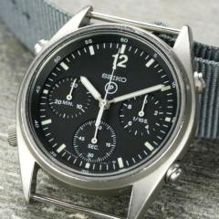
    • My experience with this Vertex is to unscrew the ring towards the back, with a screwdriver on the slot.  The Crystal can then be pushed back.
    • Ahh the master mangler, we have a new member here that met him.
    • Instead of creating a million threads, I figured I'd keep my notes and questions bundled up here. I'm working on the barrel at the moment, and it appears to have a detached bridle like my 1954 Bulova 10BPAC, but also has an attached bridle. The detached bridle is also extremely thin, and in fact doesn't even show up on the photo I took. According to the tech sheet: So my questions three: 1. Should the slip ring always be replaced as suggested, or can it be cleaned and reused? 2. Is braking grease still used, and if so would it be on the inside or outside of the slip ring? 3. Do I need to go out and buy dry lubricant? I have Lubeta v105 and v106 which are supposed to dry to lubricating films. Might one of those be appropriate?
×
×
  • Create New...