Jump to content

Recommended Posts

Posted

A compound gear wheel has separated into its two component gear wheels. The smaller one, comprising the axle, was affixed to the larger (about 8mm diameter) at some 8-10 points around its centre hole with a few mm (of the hub), plus that end of the axle, protruding on the far side. I'd be grateful for advice on how to go about re-uniting the two parts. (it's actually part of a music box mechanism - I'm assuming the techniques are similar for watch gears....)

Posted
4 hours ago, RichardHarris123 said:

It looks like a staff and the pivots are broken, I would assume the wheel is riveted on. 

Are the pivots broken, or are they just cone shaped at the end like Timex pivots?

Does the wheel just need pushing back on ?

Posted
On 12/24/2023 at 6:24 PM, dnhb said:

Thanks for your interest, Mike. Photos attached.

Separated compound gear wheel -1.jpg

Separated compound gear wheel -2.jpg

It just looks like a basic drive wheel,  pinion and wheel riveted together or pressed in held by friction. How loose is the fit ? you might be able to spread the rivet out again if its still intact or close up the hole with a domed punch to friction fit again.

Posted

Thanks for your interest, Mike. Photos attached.

I can't see how to respond individually to each of your helpful responses, Folks, so this is a portmanteau response & 'thank you':  The Pivots are cone shaped at the end, not broken. Not sure what is meant by "spread the rivet out again" but it may well be that the Pinion of the smaller cog wheel was just a friction fit in the hole of the larger wheel. I'd come across the idea of closing up such a 'housing' hole with a punch before, but couldn't remember where and so wasn't sure how to do it without buckling the wheel itself.....

Posted
54 minutes ago, dnhb said:

Thanks for your interest, Mike. Photos attached.

I can't see how to respond individually to each of your helpful responses, Folks, so this is a portmanteau response & 'thank you':  The Pivots are cone shaped at the end, not broken. Not sure what is meant by "spread the rivet out again" but it may well be that the Pinion of the smaller cog wheel was just a friction fit in the hole of the larger wheel. I'd come across the idea of closing up such a 'housing' hole with a punch before, but couldn't remember where and so wasn't sure how to do it without buckling the wheel itself.....

Some components are held together by a flange that is attached to one of the parts . That part would be inserted through the hole and the flange spread out and folded over so it grips the adjoining part. Tbh this just looks like its friction fitted and would be inserted under pressure.  If the hole is slack fit it could be closed up with a wider domed punch. 

Posted
On 12/30/2023 at 4:01 PM, CYCLOPS said:

that wheel is press-fit onto the pinion, if loose you can flatten or peen the hole smaller with a round faced punch from a staking set, I hope this helps 

I've just invested in an old K&D 600 series staking tool set in order to do this.....

On 12/30/2023 at 11:54 AM, Neverenoughwatches said:

Some components are held together by a flange that is attached to one of the parts . That part would be inserted through the hole and the flange spread out and folded over so it grips the adjoining part. Tbh this just looks like its friction fitted and would be inserted under pressure.  If the hole is slack fit it could be closed up with a wider domed punch. 

Thanks for explaining that - I've found an illustration on YT of this being done.

  • Like 1
Posted

that is still one of the best staking sets, you won't be sorry you found it, there is a booklet/leaflet that explains how to use the different punches and stumps also....

Posted
2 hours ago, CYCLOPS said:

that is still one of the best staking sets, you won't be sorry you found it, there is a booklet/leaflet that explains how to use the different punches and stumps also....

 Thanks. After a bit of research within this & other Forums, I thought the K&D Inverto facility was a key feature along with the reasonable availability of stakes & stumps, K&D's reputation and, as you say, the available documentation (e.g  https://archive.org/details/KDStakingTools/page/n17/mode/2up & at https://kanddinverto.weebly.com/junior-inverto-600.html). With no real idea about value for money (although I know there are other watch repairs I'll be using it for) but assuming it might be an appreciating asset in the long term, I paid £268 (inc P&P) for a set with 76 (out of 100, judging by the 'holes') stakes and 15 (out of 20) Stumps with a box albeit missing 2 handles & original latch but otherwise in apparently good condition. I could have bought a new, Indian-made boxed set for £375 with 120/20 items or waited for a complete K&D set to turn up but I feel, as you imply, that I've made the right decision- as they used to say of a Rolls Royce purchase: "the Quality remains long after the Price has been forgotten".

  • Like 2
Posted
On 1/3/2024 at 10:46 PM, dnhb said:

Thanks for explaining that [ i.e. "Some components are held together by a flange that is attached to one of the parts . That part would be inserted through the hole and the flange spread out and folded over so it grips the adjoining part. Tbh this just looks like its friction fitted and would be inserted under pressure.  If the hole is slack fit it could be closed up with a wider domed punch." ]

Bearing in mind your comment, on firing up my Adonstar magnifier I found that there was a 'castellated' flange at the end of the cogged pinion of the smaller part although the flange length wasn't long enough to be folded over on the far side of the big wheel once inserted. However, your comment caused me to push out the flange from its slightly folded-in state - which I did using a round nose hollow stake (K&D #80) - press the piece into the larger wheel & then re-tighten the connection with the #80 stake. The compound wheel is now re-installed in the music box mechanism which is now working !

  • Like 2

Join the conversation

You can post now and register later. If you have an account, sign in now to post with your account.
Note: Your post will require moderator approval before it will be visible.

Guest
Reply to this topic...

×   Pasted as rich text.   Restore formatting

  Only 75 emoji are allowed.

×   Your link has been automatically embedded.   Display as a link instead

×   Your previous content has been restored.   Clear editor

×   You cannot paste images directly. Upload or insert images from URL.

  • Recently Browsing

    • No registered users viewing this page.
  • Topics

  • Posts

    • Yeah I figured that one out when I googled and realized that my spindle is actually from Horia. It's smooth with no screwable cap.
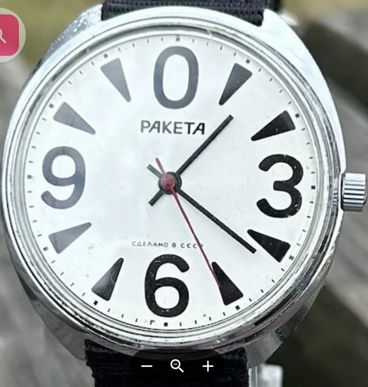
    • I am puzzled by something a snipped out something from your image and what exactly disassemble tell us? my confusion is the symbol for FHF looks like image I have below year symbol as a star and righted this instant are not finding what that means? I suppose we could use the fingerprint system to verify it really is what it claimed to be. Size itself is really interesting there's almost no watches in that particular size. Then were missing details in the photograph above like diameter of movements to verify it really is the size and are missing the setting components.   went to the bestfit book looking at the symbols didn't see it. Look at the link below I did find it back to the bestfit book and yes it really is there https://reference.grail-watch.com/documents/history-of-ebauches-sa/ then bestfit book says lists the size as 10 1/2. one of the problems with vintage watches is finding parts yes a donor watch would be good.
    • Actually, this could be the issue. Drag from the module could be overcoming the cannon pinion. It was definitely not at the point that the driving wheel was loose on the cannon pinion, it took a little bit of effort to rotate it when applying the grease. Maybe I need to look again at applying oil to the pivots.    Yeah, it's very annoying. I don't want to give up on it, so back on with it over again until I catch a break. 
    • The sping is not pushing directly on the cap, but is pushing against the spindle. So, even if the usual black cap is replaced with the micrometer cap, the spindle is still pushed up.
    • But he tells that the micrometer cap doesn't screw into the spindle. How can the spring push the spindle up if there's nothing to grip? There is a screw visible on top of the micrometer cap so should it be able to screw into the spindle? I'm feeling really dumb now. Does anyone manufacture that cap as an aftermarket item? Might be worth investing. Ok so the spindle is different, now I get it.
×
×
  • Create New...