Jump to content

NH35 Hairspring Repair Techniques


Recommended Posts

Hello Watch Repairer 
After having disassembled and reassembled an ETA6497 clone movement, I am now practicing on something smaller and that is the NH35 movement. Unfortunately, when I disassembled the balanced wheel, the spring has deformed. I have now got a replacement. Unfortunately, I have not found good information on how to replace such a hairspring correctly. The videos I have found the spring is screwed. On the NH35, I think the spring is clamped. Diese Uhrwerk dient für mich nur als Übung .Does anyone know about this movement and can give me some tips or tell me how to align these pins? What should I pay attention to? This movement is just an exercise piece for me .
Thank you


Pins 1.jpg

pins 2.jpg

hairsping fault.jpg

Replacement Spring.jpg

Link to comment
Share on other sites

https://docs.google.com/presentation/d/1A5rQM7MtebExRApg6elWTTBaIS_psTu1/edit?usp=share_link&ouid=102423790676520463184&rtpof=true&sd=true

This document is not mine but I i thought I should share this to you. It covered almost everything you need to know about Etachron, remove, install, adjusting, etc... and there are videos inside. Go slow and be patience and you should be able to do it. Just one more thing I want to add which is my own experience, I found that balance complete replacement parts for these Seiko movement or ETA movement aswell is not really perfect ready to go, the hairspring overcoil needed some adjustment. As you can see the distances are slightly not equal in your replacement hairspring overcoil:292390026_1488864078_ReplacementSpring.thumb.jpg.a8cce657c22c011897fab74fadc4350c(1).jpg.5c7f4bd73a4336eaa97d0d8c8e36444f.jpg

If you don't make any adjustment to correct that your hairsping will look like this once installed:

1.thumb.jpg.58c27adc6d24264a9a4ded62d51ba9a3.jpg

Here is the final result. To me this looks idea. You can't correct this imperfection by rotating the stud carrier, bent has to be make to the hairspring. Make sure that, 1. All coils are evenly spaced, 2. The balance pivot should rest right at the center of the balance cock jewel hole, 3. The hairspring is dead flat and parralel to the balance cock and mainplate. Then you just have to adjust the Etachron regulator following the document.

2.thumb.jpg.9da07f342b29b2b71eca625735625a61.jpg


Edited by ColdWind
  • Like 1
  • Thanks 1
Link to comment
Share on other sites

21 hours ago, ColdWind said:

This document is not mine but I i thought I should share this to you. It covered almost everything you need to know about Etachron, remove, install, adjusting, etc...

Thank you for this guide, it's really great and now I understand the logic behind it. I would like to donate something to the author of this guide. 🙂 He gave himself a lot of effort and shared his knowledge. I appreciate that very much.


I have now spent over 3 hours analyzing and implementing the whole thing. But I noticed that my regulator pin doesn't look like it does in the guide. The pin of my balance cock is a bit shorter and I can't squeeze it because it's too thick. If I did that, the spring would no longer burst. When I tried to press the pin, I damaged the pin a bit and had to adjust the spring again, which was also very difficult.

Can it be that the pin does not have to be pressed with this version? What will be very difficult during installation is not to damage the spring.

Pinside.jpg

RegPin.jpg

How does it it look? How to squeeze the pin without damaging the hairspring? Maybe someone has a good idea... 

Hairspring 2.jpg

Link to comment
Share on other sites

4 hours ago, manjo said:

Thank you for this guide, it's really great and now I understand the logic behind it. I would like to donate something to the author of this guide. 🙂 He gave himself a lot of effort and shared his knowledge. I appreciate that very much.


I have now spent over 3 hours analyzing and implementing the whole thing. But I noticed that my regulator pin doesn't look like it does in the guide. The pin of my balance cock is a bit shorter and I can't squeeze it because it's too thick. If I did that, the spring would no longer burst. When I tried to press the pin, I damaged the pin a bit and had to adjust the spring again, which was also very difficult.

Can it be that the pin does not have to be pressed with this version? What will be very difficult during installation is not to damage the spring.

Pinside.jpg

RegPin.jpg

How does it it look? How to squeeze the pin without damaging the hairspring? Maybe someone has a good idea... 

Hairspring 2.jpg

Oh you don't have to squeeze the regulator pin with this version. I should have mentioned it. If the hairspring could came out from the pin without the need to squeeze anything then you just guide the spring back to the pin and it's done.

  • Like 1
Link to comment
Share on other sites

12 minutes ago, ColdWind said:

Oh you don't have to squeeze the regulator pin with this version. I should have mentioned it. If the hairspring could came out from the pin wit

ok. I will try to install the balanced wheel back in the movement and hope it works. 🙂


Link to comment
Share on other sites

On 1/23/2023 at 4:14 PM, ColdWind said:

Oh you don't have to squeeze the regulator pin with this version. I should have mentioned it. If the hairspring could came out from the pin without the need to squeeze anything then you just guide the spring back to the pin and it's done.


Since individual spare parts are not worth it, I had ordered a new movement as a replacement weeks ago. Unfortunately, I noticed yesterday that after winding the movemenr, the balance works only briefly. After 30 seconds, the balance wheel swings slower until it finally stops. Does you now what I have to pay attention to during disassembly?

Link to comment
Share on other sites

Join the conversation

You can post now and register later. If you have an account, sign in now to post with your account.
Note: Your post will require moderator approval before it will be visible.

Guest
Reply to this topic...

×   Pasted as rich text.   Restore formatting

  Only 75 emoji are allowed.

×   Your link has been automatically embedded.   Display as a link instead

×   Your previous content has been restored.   Clear editor

×   You cannot paste images directly. Upload or insert images from URL.


  • Recently Browsing

    • No registered users viewing this page.
  • Topics

  • Posts

    • Right now I'm making do with a similar micrometer (the one below is $45 shipped but you can find better deals) and a $20 stand. You do have to be excruciatingly careful measuring jewels, since there's no table, but if you don't have the $500 to throw around, it's a nice option.
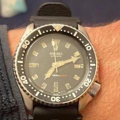
    • As  I kid, I'd watch Godzilla stomping over buildings and cars and I'd think to myself: Tokyo is a really dangerous place to live... . Cool watch!!
    • Next one up an AS 554, looks like a bit more to this one. First job is to check thickness, most springs are somewhere between .3 and .4, this one measures .35, that matches in with the .4 spring steel i ordered. So for marking up a permanent marker comes in handy to colour up the steel to be marked later with a scriber once its dry. Bestfit provide the extra bit of info for the jumper spring that is missing.
    • Thanks again, Marc.  Super helpful. I was wondering what the hole was for, and now it makes perfect sense. With your help and the other members here, it looks like I'm good to go with my Seitz tool set. I had to order some replacement pushers, but with those, the set is complete and in good condition. Now, I need to figure out what tool to buy to measure jewels (amongst other watch-related parts). I had my eye on the JKA Feintaster micrometers, but people get crazy bidding on them for $400-600 USD. I was thinking of just a regular digital micrometer (Mitutoyo). Thoughts?  Mahalo. Frank      
    • Yep, that's exactly how it should fit. The reamer shank is tapered and the socket in the spindle is also tapered so that the one centers in the other and is gripped tightly. If there is any wobble when the reamer is seated as far it will go then there is a problem. The cross hole in the spindle is to allow you the push the reamer back out again. If the reamer seated much deeper then it would limit the access for pushing it back out again. Here is one of mine for comparison.
×
×
  • Create New...