Jump to content

Recommended Posts

Posted

Hi - I recently serviced a JeanRichard JR1000. I was unable to find any technical documentation in the usual locations, so I had to wing it. In the end, there were no real surprises, except the reassembly of the power reserve mechanism was a but tricky. I invented my own procedure for this which I will explain later. This watch is a limited edition - #13 of 50 produced. On arrival the watch would not run for more than a few seconds.

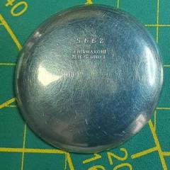
Front View Back View


After removing the back, you can see here that the movement is secured with 4 case clips. The screws on the outer perimeter seem to secure the crystal/bezel to the case proper. That said, after removing them I was unable to separate the case. I decided to leave it be instead of risking damage. Once I removed the case screws and clips, the movement and its retainer were easily removed. Next step was to remove the hands in the normal fashion.

DSC_1330.thumb.jpg.c41efc9eb3f1863f4787a85e8583c286.jpgDSC_1331.thumb.jpg.84289b31989253d2de62f889174ef028.jpg


Removing the 2 screws indicated by tweezers below freed the movement from the substantial retainer. This assembly really holds the movement VERY securely in place.

DSC_1333.thumb.jpg.117a6dcb878d71379a33a2f7931cbc86.jpgDSC_1332.thumb.jpg.d5caa9bd40cde321307faa6dc95e8e42.jpg

DSC_1334.thumb.jpg.636c7cfdeb5f8a4bc93bb922f0bd161e.jpgDSC_1335.thumb.jpg.e4fd5a5c8fd160cff50ee11160f24321.jpg


Removing the dial is done in the normal fashion - 2 screws on the side of the movement (not shown). Once removed you can see the power reserve mechanism along with connecting lever that couples the mechanism with the power reserve indicator hand.  I removed the plastic "track" that the indicator lever travels in by removing the 2 small screws and lifting up. Not pictured below, the lever is also easily removed from the plastic traveler. There is another component that the lever attaches to on the underside. Make sure you pay attention to the orientation of this component when removing - it is asymmetric. I failed to do this, but it's pretty simple to deduce the correct orientation on assembly.

DSC_1336.thumb.jpg.fec3db62931d0e8781be01de736488c8.jpgDSC_1346.thumb.jpg.414de4040f39fd8a57fe252a5cb9325c.jpg


Also - remove the thin plastic (teflon?) sheet that I assume is a friction reducer.

DSC_1348.thumb.jpg.3dc492e067444a1b5861ef2a061dabc1.jpgDSC_1347.thumb.jpg.01248266e26e4f60b394e88ba791d381.jpg


The rotor is removed by removing the 3 small retaining screws.

DSC_1337.thumb.jpg.c858364d8bb631a30627c9b5546adaae.jpgDSC_1338.thumb.jpg.b72afdcb0eef02c47c65ece660da9db9.jpg


Next up is the reversing wheel - part of the automatic mechanism. Remove the screw indicated below, slide the retaining clip out and then remove the wheel.

DSC_1339.thumb.jpg.bbc1217269a916e08d431af74b75cd7a.jpgDSC_1340.thumb.jpg.00e056e8d518e6b6f03856b2a77acb77.jpg


Here's the underside of the reversing wheel. On reassembly on treated with Lubeta V105.

DSC_1341.thumb.jpg.c7f491a8707d984ccb7092900460b71b.jpg


Remove the balance and pallets - normal procedure - obviously after letting down the power in the mainspring!  After removal, I put a slight wind on the
mainspring, but no power was transmitted to the train - so clearly there is something very wrong here! That said, I don't see anything obvious in terms
of broken teeth, loose parts, etc.

DSC_1343.thumb.jpg.18a5121a262e7ca01251770770bcb10c.jpgDSC_1344.thumb.jpg.4115441df95a986622abece18f198afd.jpg


Remove the train bridge and then remove the balance hack (pointed to by tweezers)


DSC_1350.thumb.jpg.89ec0a7aad98c6c218d296b6d26994b1.jpgDSC_1352.thumb.jpg.36b218582deb543a9fa6649ce51fe3cc.jpg


There's a bit of disassembly to do on the reverse side of the train bridge. Start by removing the single blue screw and the small bridge that it secures.

DSC_1355.thumb.jpg.d07df9f54cb2c639cee5390f095bff04.jpgDSC_1404.thumb.jpg.feb2fea29715f02e9f719ba33274bf67.jpg


Remove the 2 small brass gears.

DSC_1405.thumb.jpg.261857de50d4a12049dc4e1a01bfd639.jpgDSC_1406.thumb.jpg.a5dc5d6a6229fcb616c0136309b8237a.jpg

And the remaining components. Note the dial washer that sits beneath one of the gears.

DSC_1408.thumb.jpg.9fdc9cafa8f0a06645474c6421b4c10a.jpgDSC_1409.thumb.jpg.d199895c557ec7712ae36b7b66d0b853.jpg


Remove the escape wheel and the barrel bridge.

DSC_1353.thumb.jpg.024fe54482ab78d4880242c10789b49a.jpgDSC_1356.thumb.jpg.1fbcacf240d476311ebffd490cfe4343.jpg


The click and clickspring are on the reverse side of the barrel bridge. They should be removed (no pic)

DSC_1387.thumb.jpg.cec7697cf012804891fa65a93488db58.jpgDSC_1358.thumb.jpg.cc46882876de703754eca08721bb1a56.jpg


Remove the train gears and the center seconds pinion. And at this point I see the issue with the movement. The barrel is frozen in place. The 
lower bearing seems to have some material, like gunk, that has seized up and is restricting its movement. I had to use a bit of force to dislodge 
the barrel from the main plate. I didn't see any notable permanent damage - just a large deposit of dirt and grease.

DSC_1361.thumb.jpg.5321ae6999c2ed202a95d03bfe20f719.jpgDSC_1367.thumb.jpg.e69e79b414cbb5ee1460ad19713d440e.jpg


After wrestling the barrel from the main plate, remove the arbor and spring. Note the arbor has a small independently rotating section on it as well.
You can see it as brass on in the pic below.

DSC_1391.thumb.jpg.57cea46111efcf5f3f68f3139c296de7.jpgDSC_1393.thumb.jpg.8eac071dcadfba62b8b667d4eaa84a06.jpg

DSC_1392.thumb.jpg.5200f2de864ea77c756164e86fe5b9c6.jpg


So far so good - let's flip the movement over and focus on the dial side. This power reserve mechanism requires some exploration. I am using the 
tweezers below to point out the orientation that the mechanism is in when there is no power in the mainspring. Note that I actually took this pic
before disassembling the other side of the watch - while the barrel and train were still in the watch. Remove the 2 small screws and the retaining 
plate.

DSC_1363.thumb.jpg.bfc019dd0b91b96721e3ecbdcb61ea7b.jpgDSC_1365.thumb.jpg.751f799dab418bdf607f71c98420bc0d.jpg


Lift the mechanism as a unit out of the watch. You need to wiggle it a bit to get it out. The reason for this will be apparent soon.

DSC_1366.thumb.jpg.dded6a79c32c10a613cbe66b6897fe5a.jpgDSC_1369.thumb.jpg.b381ec4b81c219859276622486d2cc83.jpg


The small gear remaining below actually fits between 2 of the gears in the mechanism removed above.

DSC_1371.thumb.jpg.6dcf557abd3823685830f93d83811b1f.jpgDSC_1372.thumb.jpg.955b216b0a4bbcc7a520d8ddc2c4df3d.jpg


The reverse of the reserve mechanism. Nothing to disassemble here - I just cleaned it as a unit.

DSC_1370.thumb.jpg.46cd211ad32335a2fa8187d10b1d4c7d.jpg


Remove the 3 screws and the calendar plate.

DSC_1373.thumb.jpg.acf6a3cd20ceb97be5fa38e0d9b3ee1e.jpg

DSC_1374.thumb.jpg.dab2ba635d7f1b399c1f97fa1605ddfa.jpgDSC_1375.thumb.jpg.e7a413cd69ec8a4338503ea91e991d71.jpg


Remove the hour wheel and the two date maintaining plates, followed by the date ring.

DSC_1376.thumb.jpg.9ba49d8672238b88a11d86c0779e3b12.jpgDSC_1378.thumb.jpg.a14c13095fa65604226fac4bebe5ad87.jpg

DSC_1379.thumb.jpg.c38c6a444d78f709ab3b99f0133d950d.jpgDSC_1381.thumb.jpg.a564bebb6f4a3dc95cfc8ea62bd7741c.jpg

DSC_1382.thumb.jpg.2eb04549f2a7bc45a46268c7d0483bd7.jpgDSC_1383.thumb.jpg.6a8ca40ae436d82cabd4efc01713ce65.jpg


Remove the minute wheel, intermediate gears and the date change gear. We also remove the date jumper and the small date setting gear that is held in place
by the jumper.

DSC_1384.thumb.jpg.c27cef0ad454394e9c1e2527dca81c18.jpgDSC_1385.thumb.jpg.cc884d36d0fd43f6e538e17ef5064185.jpg


Remove the cannon pinion and its attached gear along with the date advancement gear. We now have just the keyless work remaining!

DSC_1386.thumb.jpg.d4b49735d483e023c937944fccbf6318.jpgDSC_1394.thumb.jpg.3497030198c38a3323468acd05796df1.jpg


Next up is the setting lever spring

DSC_1395.thumb.jpg.7e7cb53f086dbdbb2e24443cabe81bc7.jpgDSC_1396.thumb.jpg.f394567fcf82272b8a41fffe6beca61a.jpg


Next remove the yoke

DSC_1397.thumb.jpg.8c318ac21824f031b459880ca0f39f08.jpgDSC_1398.thumb.jpg.ce71079cbbf5d45f11d2110c36f9efe7.jpg


Now the setting lever and the remaining lever. Finally the winding pinion and the sliding pinion.

DSC_1399.thumb.jpg.19424e0672b70766a6c004fa2172552b.jpgDSC_1400.thumb.jpg.2ae9e1a57718d088a5f7ebf0159349f1.jpg

DSC_1401.thumb.jpg.deb469b63116ae962b11b3382b97ad56.jpgDSC_1402.thumb.jpg.54ee34ba42264f5ae83581b8b7847259.jpg


And that's the full disassembly of this very nice movement.

I mentioned earlier that I needed to be a bit creative reassembling the reserve mechanism. Since the reserve mechanism is replaced after the calendar plate is installed,
the jewels on the dial side must already be lubricated (since they will be hidden by the calendar plate). So this implies that the barrel and wheel train are already installed.
Problem is that with the barrel installed it is very difficult to get the reserve mechanism seated correctly. I ended up doing the following:

1. Reassemble the wheel train and barrel.
2. Lubricate all dial side jewels and bearings
3. Install the calendar mechanism 
4. Remove the barrel and train of wheels. Note that the issue is really the barrel, but you cannot remove the barrel without also removing the train
5. Now it is trivial to install the reserve mechanism and orient it as mentioned at the time it was disassembled
6. Taking care not to allow the reserve mechanism to rotate (and become misaligned), reinstall the train and barrel
 

And that's all there is to it!
 

Hopefully someone finds this useful. At the end of the day, the watch now runs perfectly after a good cleaning and lubrication.

Stu...


DSC_1351.jpg

DSC_1407.jpg

DSC_1408.jpg

DSC_1354.jpg

DSC_1355.jpg

DSC_1357.jpg

DSC_1389.jpg

DSC_1392.jpg

DSC_1362.jpg

DSC_1383.jpg

  • Like 3
  • Thanks 1
  • Recently Browsing

    • No registered users viewing this page.
  • Topics

  • Posts

    • I believe @nickelsilver has a setup like that.
    • I posted pictures earlier in this thread. My lathe and mill are two separate instruments. I think I have seen examples of putting a milling head on a lathe bed...but not certain.
    • Timex Camper, September 1994, new to me. Strap is an old perlon with "Germany" in script etched into the resin on the tail end. Not Horlon or Eulit I believe. History unknown, running strong, losing less than a minute a day. Goals for this: Wear it a ton! Buy crystal lift, clean out the gunk around the ring and under the crystal Eventually swap into a stainless steel case. I've seen a member who has swapped a Timex mechanical movement into the Timex J.Crew quartz field watch case.
    • One of the problems we would have with a watchmaker's lathe is they were made over considerable span of time and manufacturing in the early days probably wasn't as good as it was today. Then if you look at the older catalogs typically it was just the head a few collets and something to rest graver on. So basically a basic lathe with over time things acquired but acquired things may or may not fit. Order today you purchase a used lathe that all kinds of nifty bits and pieces from a seller that acquired from? This would come back to that the basic watchmaker's lathe was used for basic watchmaking like turning things with a hand graver. Then limited indexing is fine because you can make things like stems Which don't need a whole bunch indexing   In the link above the word vector is mentioned and at the link below you can purchase one. Then of course you're going to need the motor that's a little bit extra for the price. https://www.hswalsh.com/product/lathe-vector-watchmakers-48-collets-hl11. That you're going to need some bonus parts like these found this picture online show the classic way of classic gear cutting.   The lathe could have a much bigger indexing disk but it has to be mounted close to the edge. Otherwise you're going to have a whole bunch of smaller disks like this which I think has notches rather than holes. Then as wonderful as these pictures look actually cutting a gear with this is not entirely fun. Look at all is belts all pulling on things and this is a watchmaker's lathe lightweight with lots of bits and pieces attached. It would make more sense if you actually cut a gear with something like this and it tends to be it's not really the best way to do it looks nice on paper but it is not the best way to go. Reality for cutting watch parts would be a bigger machine is much better. Than getting rid of all those belts and pulleys also good. Here is an interesting channel I would've liked of found a different video but this was nice and short if you look at his video as he uses a stepping motor and worm gear assembly for the indexing plate. In this particular video it gets attached to the lathe at about one minute and seven seconds and it looks like it's hiding looks like he has a Sherline. I do know he's had other stuff you'll just have to go through his videos to find it. Then at about one minute and 22 seconds you find out if you set up things appropriately. It's always bad we end up with half a tooth at the very end. Then you will note big lathe yes he's getting a big gear but you could easily cut a watch gear with the setup. And it definitely way more stable than a watchmaker's lathe.         Oh here's a company they been in business since 1911 http://www.fwderbyshireinc.com/  
    • Hello and welcome from Leeds, England. 
×
×
  • Create New...