


-
Recently Browsing
- No registered users viewing this page.
-
Topics
-
-
Posts
-
By Latetothegame · Posted
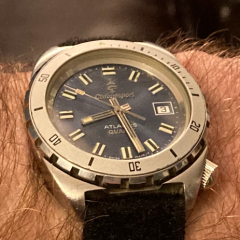
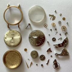
I have now successfully repaired 5 watches and I find it immensely satisfying. See the picture of the 4 pocket watches. The 2 Pocket Ben’s are Style 4 from 1939 and 1941. They used screws, not rivets on these models so I could disassemble them almost completely. I disassembled, cleaned, reassembled and lubricated them and they are running well and keeping good time. I also changed the mainsprings. The gold pocket watch was my uncles and had issues in the keyless works that I was able to repair. That was particularly rewarding as I can now pass that on down through the family. Keeps great time. The silver watch had a damaged hair spring that was not removable so I sourced a complete balance and replaced it. That has been running well also. Finally, not pictured, I replaced the quartz movement in my 40 year old Chronosport Atlantis dive watch. That has been my only wrist watch repair and I have been wanting to try some more . So I purchased a vintage Sovereign man’s wrist watch with some issues to try my hand at restoring it. Now for my question and this is embarrassing. I can’t figure out how to open the case. I have attached pictures. I believe it is a snap on case but I cannot find anything looking like a tab or slot to insert a pry tool into. I looked at pictures of Sovereign watches for sale that have the case back off and I don’t see any evidence of it being a screw on. My simple question is how do I open this thing? Thanks for your help! -
 Could you grind a scallop of material out of the two blocks that hold the blades to allow crystal clearance ? Or relocate two blades ? CJ
 -
 Mine like yours is mostly useless unless the crystal is flush and the bezel is plastic (which is easy enough to remove with a knife). A domed crystal as on a Vostok means the blades won't reach.
 -
 The crystal is facing down with the back facing up, it's just a design error with this chinese bevel remover, if i'd got it from another seller i may have got a chinese bezel remover made in another factory that passed QC and worked, this bezel remover will never work without modification. On the photos below you can see the differnce in blade layout the red tool looks like it's upto the job with blades contacting the bezel, the silver one is the one i got sent the blades are way too far apart and don't contact the bezel until the crystal is sat on the aluminium supports.
 -
 Turn it over as in the picture so the crystal side is down case back side is up. Some people put a plastic baggie so the bezel and crystal don't touch the large screws that move the tool dises in and out.
-


Recommended Posts
Join the conversation
You can post now and register later. If you have an account, sign in now to post with your account.
Note: Your post will require moderator approval before it will be visible.