


-
Recently Browsing
- No registered users viewing this page.
-
Topics
-
-
Posts
-
 Sorry @nickelsilver, I'm just seeing this now. It is a standard metric screw plate. I followed the suggestion of doing the thread cutting in a pin vise. It took me forever because the piece is so delicate that I cut and cleared chips very frequently. But eventually I did get it. Not pretty, but I got it; the first thing I ever successfully made on the lathe. I cut the screw slot with a jewelers saw. How can I ensure that the slot is centered on the screw head?
 -

-
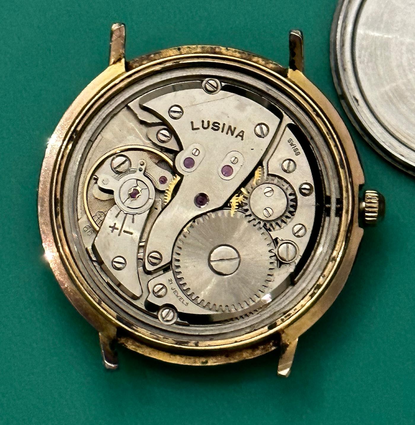
 Hello, My name is David and I’m a vintage watch collector/ wanna be hobbyist watchmaker from France. I really want to progress into my watch repairing hobby. For now, I’m only having fun servicing my own watches and spare movements, simple small 3 hands from the 50s (Omega, eterna…) Learning step by step or at least trying to 🙂
 -
 More setbacks and successes... After letting the watch run in (but before I fixed the BE) a chunk of the radium lume fell off one of the hands and pulverized leaving radioactive dust all over the dial 😞 ☢️ ☠️ So before I could continue further I decided I would remove the radium lume. I have removed radium lume from hands before where it was already starting to flake away but this time I had to work out what I was going to do with debris on the dial. I decided that getting everything under water and removing all the lume was probably the best way to go. So here is what I did... I put an essence jar I use for cleaning parts and filled it with water and put it into a big ziplock bag along with the tools I would need - a sharpened piece of pegwood and a 0.80mm screwdriver - I put on a pair of nitrile gloves and a covid style mask and then opened the back of the watch. Now with the back off the watch I could do the rest inside the bag. I removed the watch from the case and removed the hands from the dial (through the bag) and then undid the dial screws and removed the dial from the movement. I then put the hands and the dial and the watch case into the water and removed the movement from the bag. Carefully and slowly with one hand in the bag and one hand trying to poke and hold stuff through the bag I gently rubbed away the lume from the dial and hands with the pegwood. I then took the parts out of the water and removed the jar from the bag (leaving the parts still in the bag) - with the majority of the dangerous stuff now in the water I disposed of this (down the toilet) and gave the jar a good rinse in running water before refilling it and returning it to the bag where I gave all the parts another rinse in the new water. I then took the parts and put the geiger counter over the top of them and looked at them carefully under UV light to see if there were any flakes still hanging on. I dried everything with some kitchen towel. Once I was finished will all that I remved the parts from then removed the gloves and put them in the bag with the paper towels and the pegwood and thew the bag in the household waste. Finally I gave the dial, hands and case another rinse in the sink under running water. I didn't bother following up with a rinse in distilled water water because the water here is pretty clear of limescale etc and I find it doesn't mark! So here are the results of my weekends work! Timegrapher dial down (dial up is almost the same) The fixed shock setting New crystal - and lume removed from dial and hands
 -
-


Recommended Posts