


-
Similar Content
-
-
Recently Browsing
- No registered users viewing this page.
-
Topics
-
-
Posts
-

-
Put the movement in a movement holder and it will be supported as you push down on the setting lever post to release the winding stem. Make sure the post is over the shoulder of the movement holder so what you are pressing down on is supported. As a general rule, hold the movement and not the movement holder. Replace the hands when the movement isn't in the case and support the centre jewel (if it has one) on a hard surface or staking block when replacing the hands to stop the jewel accidentally moving or even coming out. A dedicated movement holder with a central jewel support is even better, but pricey
-

-
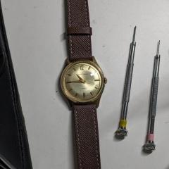
 Hi, guys I have a bit of a predicament and hopefully, somebody can advise. I'm working on a Roamer MST 521 where the movement is extracted from the crystal side. I'm now at the final hurdle where I need to replace the movement back into its case but I'm not sure of the correct procedure. I still need to fit the hands but that's where the problem lies. If I insert the winding stem to test the hands for correct alignment I will need to turn the movement over to release the stem again it's the spring-loaded type and needs a small bit of force to push down but with the hands fitted, I don't think I can do this on a cushion without causing some damage to the hands and that's the last thing I want to do, this watch has already been a love-hate relationship and I'm so close to boxing this one off which I'm counting as my first major project. The other option is to case the movement then fit the hands and hope everything is okay. I've already broken the original winding stem but managed to find a replacement, the last one in stock, so I'm a bit reluctant to keep removing it. Any suggestions would be appreciated.
 -
I would go for the dearer spring. You won't need to remove the spring from the carrier ring and then use a mainspring winder to get it into the barrel, for a start. Also that spring is closer to the needed dimensions, especially the length. The length plays a part in the mainsprings strength. If you double the length you will half the force (strength) of the spring and vice-versa. A spring with 20 mm less length would be about 7% shorter, so technically would be 7% more strength, but I find halving this number is closer to real-world findings, so the spring would be about 3 to 4% more strength/force. On a mainspring that ideally kicks out 300 degrees of amplitude, a 3% increase in amplitude would be 309 degrees. Increasing or decreasing the length of the mainspring will affect the power reserve to a greater or lesser degree. It depends how much shorter or longer it is. I've attached a lesson regarding mainsprings, focussing on the size and strength of the spring within the barrel, you might find helpful. Unfortunately it is a PDF converted from a PowerPoint presentation, but only a slide was lost that was originally a video of fitting a mainspring Lesson 5 The mainspring.pdf
-


Recommended Posts