Jump to content

Seiko 5J22A Kentic "auto Relay" Complete Service Walkthrough


Recommended Posts

Seiko 5J22A Complete Service


Hunting through my cupboards I found my old Seiko Kentic "Auto Relay" that I purchased sometime in the 90s, when this was the latest cutting edge Quartz Watch on the market offered by Seiko.


post-246-0-79144000-1407244939_thumb.jpg


It's been sitting for over a decade without use, and I decided to really push myself and, with the Lord's assistance, completely strip and service this watch. 

So I tracked down the Tech Specs, and if you are thinking of embarking on servicing the 5J22 YOU WILL NEED THEM!! :)

So here they are:

5J22A.pdf


I will be using the part names from this document for this walkthrough, so download and print it out for you own sanity.  The parts in this movement are incredibly small, so much so that my camera had trouble focusing on them ... so part names will help you as much as the visuals aids for this service.

Once again, I've had no one to guide me on this, so this is the way "I" stripped the movement down, the correct factory procedure may, and probably does, differ from my way ... so I give a warning here: CONTINUE AT YOUR OWN RISK.


Disassembly


Unscrew the back cover and store the rubber gasket away safely.


post-246-0-82696400-1407244942_thumb.jpg


With a 2.0mm Screwdriver, pry the Location Ring out with the slots provided in the plastic ring.


post-246-0-66264600-1407244945_thumb.jpg


Remove the Oscillating Weight with a 1.20mm Screwdriver ... and this will be the driver you use on all further screws.


post-246-0-38654600-1407245954_thumb.jpg


To remove the Stem, you need to have the Stem push all the way home, to move the Yoke into the correct position so you can depress the lever (Location shown in picture after I removed the movement to make it easier to see the spot where you push)


post-246-0-89386800-1407244948_thumb.jpg


The movement should now come out of the case along with the internal Bezel Ring.


post-246-0-67610100-1407244951_thumb.jpg


Remove the Hands


post-246-0-11751400-1407244954_thumb.jpg


Remove the 7 screws for the Circuit Block Cover A, and the Rechargeable Battery Clamp

(Sorry referred to an older pic to so you the location of screws)


post-246-0-26148500-1407244958_thumb.jpg


Remove the Insulator for Rechargeable Battery, and then the Battery itself.


post-246-0-99435300-1407244960_thumb.jpg


Remove Circuit Block Cover A


post-246-0-66521000-1407244963_thumb.jpg


Remove Circuit Block Cover D


post-246-0-00671800-1407244967_thumb.jpg


Reference picture of Circuit Block Cover D


post-246-0-06045700-1407245221_thumb.jpg


Remove Circuit Block Cover B


post-246-0-54105000-1407245224_thumb.jpg


Reference picture of Circuit Block Cover B


post-246-0-08397800-1407245227_thumb.jpg


Remove Oscillating Weight Bridge


post-246-0-30484200-1407245230_thumb.jpg


Reference picture of Oscillating Weight Bridge


post-246-0-76577300-1407245232_thumb.jpg


Remove Circuit Block Cover C


post-246-0-90721200-1407245236_thumb.jpg


Reference picture of Circuit Block Cover C


post-246-0-37633300-1407245239_thumb.jpg


Remove Circuit Block

NOTE: The pin with the yellow arrow pointing to it holds onto the Circuit Block very firmly.  Be CAREFULLY and GENTLE, as the Circuit Block can be easily damaged.


post-246-0-13734100-1407245242_thumb.jpg


This is the angle of attack that I recommend. Coming in on an angle just in front of the Crystal Unit, and gently push upwards ... and I mean GENTLY.  Patience wins the day!


post-246-0-52513600-1407245245_thumb.jpg


Remove the Intermediate Wheel for the Generating Rotor


post-246-0-12816500-1407247112_thumb.jpg


Remove the Generating Coil Block (grasp with tweezers where indicated with yellow arrow)


post-246-0-47060000-1407247115_thumb.jpg


Remove the Second Coil Block (grasp with tweezers where indicated with yellow arrow)


post-246-0-09602000-1407247118_thumb.jpg


Remove the Hour and Minute Coil Block (grasp with tweezers where indicated with yellow arrow)


post-246-0-73326800-1407247120_thumb.jpg


Remove the Train Wheel Bridge


post-246-0-23237800-1407247123_thumb.jpg


Remove the Second Wheel and Pinion, the Third and Fourth Wheel


post-246-0-60318800-1407247126_thumb.jpg


Remove the Intermediate Second Wheel


post-246-0-23795400-1407247136_thumb.jpg


TIP: Next is this first of three sets of Stators and Rotors that make up this Quartz Movement.

Be sure to place all the Stators and Rotors into a piece of Rodico for safe keeping.

As shown below:

THESE PARTS ARE MAGNETIC AND WILL ATTRACT PARTICLES, SO DO NOT PUT INTO THE BASKET FOR CLEANING


post-246-0-41233400-1407248689_thumb.jpg


Remove the Second Stator and Second Rotor


post-246-0-44103100-1407248654_thumb.jpg


Remove the Minute Wheel and Pinion, Intermediate Minute Wheel, and Setting Wheel


post-246-0-99403300-1407248657_thumb.jpg


Remove the Center Wheel and Pinion


post-246-0-40490400-1407248661_thumb.jpg


Remove the Generating Stator and Generating Rotor


post-246-0-07651900-1407249169_thumb.jpg


Remove the Setting Lever Spring


post-246-0-37245600-1407248673_thumb.jpg


Remove the Yoke and Setting Lever

Note: Release tension on the Yoke Spring FIRST


post-246-0-34923300-1407248676_thumb.jpg


Remove the Clutch Wheel and the First Intermediate Wheel for Calendar Corrector


post-246-0-05753600-1407248680_thumb.jpg


Remove the Hour and Minute Stator and Hour and Minute Rotor


post-246-0-59750900-1407248683_thumb.jpg


This side of the Main Plate is now finished ... time to flip it over and start on the Calendar Works


post-246-0-55734700-1407248686_thumb.jpg


Remove the two screws indicated and remove the Hour Wheel Guard Spring, and the Date Dial Guard


post-246-0-89597500-1407250498_thumb.jpg


Remove the Intermediate Date Driving Wheel


post-246-0-97674100-1407250501_thumb.jpg


Remove the Intermediate Hour Wheel, and Hour Wheel


post-246-0-05826500-1407250505_thumb.jpg


Remove the Date Dial


post-246-0-03678300-1407250508_thumb.jpg


Remove the Day-Date Corrector Wheel, Second Intermediate Wheel for Calendar Corrector, Date Driving Wheel and Spring

Note the position of tension of the Date Driving Wheel Spring (bottom of page 9 in the Tech Specs)


post-246-0-21175200-1407250511_thumb.jpg


Remove the Circuit Block Spacer


post-246-0-97867400-1407250513_thumb.jpg


... and the disassembly is complete!


post-246-0-17258100-1407250517_thumb.jpg


I started work on this rather late at night and took my time and studied each part before removing, making sure to document everything carefully.  So I'll clean the parts and begin reassembly fresh tomorrow.  I can see this one is really going to push my abilities, and I'm looking forward to tackling it and uploading the reassembly steps.

  • Like 4
  • Thanks 1
Link to comment
Share on other sites

Ok, back to work ...


Cleaning


I went through all the parts with a small compass to check if they were magnetized, as you don't want to put any parts that are magnetized into your cleaning machine.

Simply move the parts near to the East or West of the compass and see if the North or South moves to point to your part ... if it does you'll need to clean it by hand.


DO NOT WASH THE BATTERY, BATTERY INSULATOR, COIL BLOCK, CIRCUIT BLOCK ... I hope this is  obvious, but better to add the warning than not. 

Rule of thumb, if in doubt, leave it out!


post-246-0-18045100-1407290212_thumb.jpg


After going through all the parts here is what I had left.


post-246-0-75030100-1407290243_thumb.jpg


All other parts, including the Plastic Parts, Stators and Rotors will be cleaned with a fresh piece of Rodico.


post-246-0-14283800-1407290230_thumb.jpg

post-246-0-89868300-1407290226_thumb.jpg

Link to comment
Share on other sites

Assembly


Place the Circuit Block Spacer onto the Main Plate


post-246-0-27284900-1407351513_thumb.jpg


Clean all the Stators and Rotors before you re-assembly them ... yes they are that small!!


post-246-0-12484100-1407351515_thumb.jpg


Fit the Hour and Minute Stator, and Hour and Minute Rotor


post-246-0-94266500-1407351517_thumb.jpg


Fit the Clutch Wheel and the First Intermediate Wheel for Calendar Corrector


post-246-0-77400200-1407351873_thumb.jpg


Fit the Stem


post-246-0-84377000-1407351530_thumb.jpg


Replace the Train Wheel Setting Lever, Yoke, Setting Lever, and Setting Lever Spring


post-246-0-28756400-1407351534_thumb.jpg


Fit the Generating Stator and Generating Rotor, and also the Second Stator and Second Rotor


post-246-0-68434500-1407351537_thumb.jpg


Next is the Train and Motion Work, it is by far the hardest part of the assembly.  It is all housed under one plastic bridge, so to make it easier here is a location chart.


post-246-0-99672500-1407351540_thumb.jpg


First the Motion Work - Setting Wheel, Intermediate Minute Wheel, Minute Wheel and Pinion


post-246-0-25567000-1407355869_thumb.jpg


Slide the Center Wheel and Pinion in the affix the Spacer


post-246-0-29786400-1407351548_thumb.jpg


Then add the Train - Third Wheel and Pinion, Intermediate Second Wheel, Fourth Wheel and Pinion, Second Wheel and Pinion


post-246-0-14310600-1407353031_thumb.jpg


Place the Train Bridge on and locate all the gears into their jewel holes.


post-246-0-88867900-1407353034_thumb.jpg


Next steps are easy, but be careful and gentle

Fit the Coil Blocks - Generating Coil Block, Second Coil Block, Hour and Minute Coil Block

Then CAREFULLY fit the Circuit Block


post-246-0-40953000-1407353039_thumb.jpg


Place the Oscillating Weight Bridge; but do not screw down.

Then fit the Circuit Block Cover B, and only fasten screws indicated by yellow arrows.


post-246-0-82475800-1407353866_thumb.jpg


Place Circuit Block Cover D but do not fasten


post-246-0-94577800-1407353045_thumb.jpg


Continue and fit Circuit Block Cover C, this one you can screw down ... sorry forgot to take a photo, but it's the only cover left


Now place the Circuit Block Cover A Cover on and fasten down all the screws

Remember to leave the Battery Screw out ... as shown in the picture below


post-246-0-82869700-1407353052_thumb.jpg


Flip the movement over and fit the Hour Wheel, then the Intermediate Hour Wheel

NOTE: I pictured the Intermediate Hour Wheel upside down ... sorry about that.


post-246-0-36110000-1407353056_thumb.jpg


Fit the Intermediate date Driving Wheel


post-246-0-51063400-1407353059_thumb.jpg


Replace the Date Driving Wheel, and the Date Driving Wheel Spring (Note spring location)

Replace the Day-Date Corrector Wheel (See fitting instructions on Page 9 of Tech Specs)

Replace the Second Intermediate Wheel for Calendar Corrector


post-246-0-85486500-1407353062_thumb.jpg


Place the Date Dial Guard on, fit the Hour Wheel Guard Spring, and fasten


post-246-0-57030100-1407355102_thumb.jpg


Install the Battery, and then fit the Oscillating Weight


post-246-0-06828600-1407355105_thumb.jpg


Fit the Dial and Hands


post-246-0-89585000-1407355109_thumb.jpg


Case the movement back up ... and you're done!


post-246-0-27940200-1407355112_thumb.jpg


  • Like 2
Link to comment
Share on other sites

Lawson,  for a beginner you have done remarkably well,  another very interesting write-up.  With the very high cost of labour it probably would not be viable taking a Seiko kinetic to a repair shop as the cost would probably outweigh the value of the watch,  this is another advantage of being able to repair it yourself.  

  • Like 1
Link to comment
Share on other sites

With the very high cost of labour it probably would not be viable taking a Seiko kinetic to a repair shop as the cost would probably outweigh the value of the watch,  this is another advantage of being able to repair it yourself.  


I have to agree with you there Autowind, assembly of the train gears inside that plastic "gearbox" was very challenging and time consuming: with nine pivot points to line up with the jewels.  It's interesting to see in Mark's Video, were he replaced that Generator Rotor in an updated Kinetic model, the Generator Rotor is now accessible without opening the gear train ... this is a HUGE advantage and improvement in design.  So the newer Kinetics would be worth repairing; but as for a similar job on the 5J22, you'd be looking at a complete strip and considerable dollars in labour to replace the same part.  It would be cheaper to buy a replacement movement for it, then to service, which is a real shame.

Link to comment
Share on other sites

  • 1 year later...
  • 2 years later...
9 hours ago, coralnut said:

5J22A.pdf seems to be corrupted -- when I download it I get a zero-byte file.  Can anyone check on the integrity of the attachment?  thanks.

We can't fix that. Search the internet to download from another place.

Link to comment
Share on other sites

  • 11 months later...
  • 3 years later...


  • Similar Content

  • Recently Browsing

    • No registered users viewing this page.
  • Topics

  • Posts

    • As an experiment i was thinking of not hardening it to see how it fairs. Now that i have a complete template i could knock up another in half the time if this loses its elasticity. I might play about with a few pieces today to test their bending and spring properties. This was cs 100 the supplier quoted in annealed state, it was nice to work with files so I'm taking it thats its state. What you are looking seems like it would need annealing to work it. This is why i went for this stuff that cuts out that process, it was so easy to work.
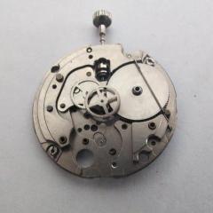
    • Showing state of hairspring on receipt, backplate & 'dished' wheel. 
    • I would harden and temper (to a light blue). It's so easy to do and only takes a couple of minutes. A search on ebay UK for "spring steel strip cs" finds plenty available in small quantites and thicknesses from 0.1mm up.  But the question is ( @nickelsilver) which "CS" number is best for watch parts ?  Also, from one of the ads : "CARBON SPRING STEEL. SIZE IS METRIC 15.00mm X 0.10mm X 304 MM  CS100 FINISH BRIGHT . HARDENED AND TEMPERD TO 480-530VPN" I've no idea about 480-530VPN. Does that mean it needs annealing before working?       Have you seen this video, he shows how to determine where the indents go ?  
    • Here is the insert ring for rectangular or elliptical movements: Note that the length is the side with the stem cut out on the spreadsheet (in the picture below this is 15.15: Here is the fake pdf file, again you need to convert to .zip after download to access the FreeCAD and 3mf files. Rectangular insert disc.pdf    
    • as you took the mainspring out what did it look like? It's amazing how much amplitude you can get if the mainspring actually has the proper shape. last week I was doing a 12 size Hamilton and was very much surprised with the beautiful back curvature the mainspring had. Then the watch had a really nice amplitude the group would be so proud it was 350 until I dropped the lift angle down to 38 that drop the amplitude quite a bit below 300. then with the beautiful back curve it still had really nice amplitude the next day. I really wish all my mainspring's look like this as the watch had beautiful amplitude the next day. So many of the aftermarket pocketwatch Springs I see now do not have anything resembling a back curve may be a slight curve and that's about all. They still work but they just don't work as nice as a properly made spring. then Omega as all sorts of nifty technical documentation unfortunately every single corner is watermarked with where it came from who downloaded it etc. very paranoid company. On the other hand I will snip out images like from the document on recycling a mainspring barrel. for instance here's the section on what your mainspring should look like. water damaged a lot of times means rust was there rust on this watch?
×
×
  • Create New...