

-
Similar Content
-
-
Recently Browsing
- No registered users viewing this page.
-
Topics
-
-
Posts
-
 Thank you for the advise!! It worked. The setting screw was a lock/unlock to remove the rotor.
 -
 I have that French tech sheet too, it is a little different than the English one (eg, it doesn't have the auto works diagram). BTW, it looks like you are looking up the case number in the 1979 ABC supplement. The 1974 ABC catalog does have the 3093 case. As you determined it takes the 1222-5 crystal. When I serviced my President 'A' (which also takes that crystal), I was able to fit a 29.8 crystal from my DPA crystal assortment. Those are, in my opinion, a great deal. The assortment comes with 10 sizes each from 27.8mm to 32.4mm in 0.2 increments. I pretty much use them for any non-armored crystal that takes a high dome crystal. I think they no longer make them but Cousins has still has some in stock but when I bought them they were around $40 for the set and now they are around $100. Still, at 40 cents a crystal it's still a good deal. For the large driving wheel, I remember I once assembled the keyless/motion works first and when I placed the large driving wheel it was interfering with the setting wheel on the dial side as the teeth were not fully meshing and it wouldn't fully seat. If that isn't the issue I got nothing and am looking forward to see how you solve it 🙂
 -
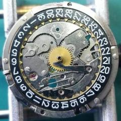
 Not sure, but just looking at it, it seems like the screw on the right may be a fake? The one on the left may not be a screw in the regular sense at all, rather a 2 position device, I think you need to point the slot towards either of the 2 dots and one will secure and one will open. Like I said this is just my best guess looking at the pictures.
 -
Hi! I am in the process of restoring a rado captain cook mkII. I want to remove the rotor, but I am not sure how to and need some help. As you can hopefully see on the photo there are 2 screws. The left one has two positions, the right one looks like a regular screw. I have tried turning the right one, but it does not give even after using more force than I would expect. Anyone know the function of the left screw with the two positions and how to remove the rotor? Thanks!!
-
 Welcome to the group Stirky. You can search for just about every subject in the craft here. Don't be afraid to ask if you can't find the answer that may have already been covered ( some ad nauseum LOL ). You don't have to buy Bergeon to get good quality. There are many decent mid-range tools available that will last you a lifetime. Cousins would be a good place to start . Cheers from across the pond ! Randy
-


Recommended Posts