Jump to content

ETA 2893-1 Service Walkthrough - Part 1 - Disassembly (repost)


Recommended Posts

Service Walk Through – ETA 2893-1 / Hamilton Khaki: Part 1 - Disassembly

This is part 1 of my service of a Hamilton Khaki – dual time zone automatic based on the ETA 2893-1 movement. I purchased the watch on eBay and it runs for a short time then stops. Looks like it could use a good cleaning.

Note that the part numbers in the images and text are consistent with those found in the ETA technical document for this movement. Disassembly of this movement is quite straightforward. The only "special" tool you need would be an oscillating weight bolt tool - and you only need this if you intend to remove the ball bearing assembly from the oscillating weight, which really isn't required. In this tear down I do use the tool - only because I recently acquired it and wanted to see how it worked :)


Off we go....


1.jpg

The dial shows evidence of some sloppy workmanship in the watch's past – several scratches from prior hand removal.


2-1.jpg

Here you see the back of the 2893-1 with its automatic rotor - nicely signed Hamilton. The arrows indicate the location of the dial screws which secure the dial to the movement. These screws have a flat. Turn them just enough so the flat is facing the dial foot and the dial pops right off. Secure the screws so they don’t pop off during cleaning.

3.jpg

Preparing to remove the hands – with a safety sheet in place.


4-1.jpg

After removing the dial, remove the Dial Support Ring (47). This ring keeps the dial the proper distance from the second timezone disc. Without it, the disc will rub against the dial.


5-1.jpg

Remove the second timezone disc, or what ETA calls the Universal Hour Indicator (46) from the center. This is a bit tricky as there’s no obvious place to grip it. I used two very small screwdrivers on each side to lift the indicator straight up. Be careful not to scratch it!


6-1.jpg

With the disc removed, we can now remove the Dial Washer / Friction Spring (45), Corrector Setting Wheel (44) and Hour Indicator Driving Wheel (43).


7.jpg


9.jpg


8.jpg 


10-1.jpg

The Hour Wheel (42) can now be lifted off, followed by the Additional Indicator Maintaining Plate (41).

11.jpg


12-1.jpg

Next components to remove are the Date Indicator Maintaining Plate (40) and the Minute Train Bridge (35).


13-1.jpg


14-1.jpg

We move on to remove the Intermediate Date Wheel (39). The Date Jumper (38) has also been exposed when we removed the maintaining plate, so we remove it. Finally, we remove the Date Indicator (37) and the Date Indicator Driving Wheel (36).


15.jpg

16.jpg


17-1.jpg

Now on to some of the motion and keyless work. We remove the Minute Wheel (34)Cannon Pinion with Driving Wheel (33)Double Corrector (32), Date Corrector Intermediate Setting Wheel (31) and Setting Wheel (30).


18.jpg


19.jpg

This side is almost complete. We leave the setting components in place. Removing them now would be problematic as we have yet to release tension from the mainspring.


20-1.jpg

21-1.jpg

Flip the movement over and remove the automatic work. After removing the 3 blue screws (seen in the previous 2 pics) we lift the entire unit up gently by the Oscillating Weight (28).


22.jpg


23-1.jpg

With the automatic work out of the way – I notice that the Stop Lever (Hack) is missing! Will try and source one.


24-1.jpg

Back to the automatic work. Removing these 3 small screws will allow the oscillating weight to come off the Automatic Framework (21).


25.jpg


25.1.jpg

This is a special tool designed to release the Oscillating Weight Bolt


26-1.jpg

I remove the Oscillating Weight Bolt (28-3) and free the Ball Bearing (28-2) from the Oscillating Weight (28-1). There was no compelling reason to disassemble this portion of the movement, but the tool worked as expected!


27-1.jpg

With the Oscillating Weight out of the way, remove the Auxiliary Reverser (27).


28.jpg


29-1.jpg

Flip the unit over once again and remove the screw and Automatic Device Lower Bridge (26).


30-1.jpg

Remove the Reverser (25), Reverser Wheel (24), Reduction Wheel (23) and Intermediate Reduction Wheel (22).


31.jpg


32.jpg

A view of the underside of these components – handy when trying to remember which way to reassemble.


33-1.jpg

Remove the single screw and gently lift off the Balance Assembly (20) with the Balance Complete (19).


34.jpg


35-1.jpg

Carefully let the power down by releasing the Click (12-6) and slowly letting the crown wind down.


36-1.jpg

 Remove the Pallet Bridge (18) and Pallets (17).


37-1.jpg

Remove the Train Wheel Bridge (16). It is secured with a hefty screw!


38.jpg


39-1.jpg

Remove the Fourth Wheel (15), Third Wheel (14) and Escape Wheel (13).


40.jpg


41-1.jpg

Remove the 3 screws and the Barrel Bridge (12)


42.jpg


43-1.jpg


Flip the bridge over and lift off the Ratchet Wheel Driving Wheel (12-2)


44-1.jpg

Remove the screw and the Click Plate (12-7), followed by the Click (12-6), Intermediate Ratchet Wheel (12-5), Intermediate Crown Wheel (12-4) and Crown Wheel (12-3). Note that the Intermediate Crown Wheel is under the Click Plate. When I removed the plate, the wheel was stuck to it due to some old oil.


45.jpg


46.jpg

Here you can see the Intermediate Crown Wheel as it was stuck.


47-1.jpg

This shows the proper placement of the wheels.


48-1.jpg

Remove the Ratchet Wheel (11), the Mainspring Barrel (10) and Intermediate Wheel (9). Note the scrap of tissue that found its way onto the movement. I was so focused on taking pics that I didn’t notice.


49.jpg


50.jpg

Pop the lid off the Barrel


51.jpg

 Remove the mainspring arbor


52.jpg

And finally, remove the mainspring, leaving the empty barrel


53.jpg

The movement side is now completely bare. Let’s flip it over and finish off the keyless work.


54-1.jpg

Unscrew and remove the Setting Lever Jumper (8), Yoke (7) and the Setting Lever (6)


55.jpg

56.jpg


57-1.jpg

Remove the Date Corrector Operating Lever (5), Winding Stem (4), Winding Pinion (3) and the Sliding Pinion (2)


58.jpg


59.jpg

All stripped down


60.jpg

Ready for the Ultrasonic!!!


Hope you enjoyed this. In case you are interested, photo equipment used was:


Camera: Nikon D5300 DSLR

Lens: Nikon   AF-S VR Micro-NIKKOR 105mm f/2.8G IF-ED,

Shutter Release: Nikon ML-L3 Remote Shutter Release (wireless)

Lighting: Polaroid Macro LED Ring Flash

Tripod: Vanguard Alta Pro 263AB 100


  • Like 6
  • Thanks 1
Link to comment
Share on other sites

  • 1 month later...
On 12.7.2016 at 2:02 PM, sstakoff said:

Service Walk Through – ETA 2893-1 / Hamilton Khaki: Part 1 - Disassembly


This is part 1 of my service of a Hamilton Khaki – dual time zone automatic based on the ETA 2893-1 movement. I purchased the watch on eBay and it runs for a short time then stops. Looks like it could use a good cleaning.


Note that the part numbers in the images and text are consistent with those found in the ETA technical document for this movement. Disassembly of this movement is quite straightforward. The only "special" tool you need would be an oscillating weight bolt tool - and you only need this if you intend to remove the ball bearing assembly from the oscillating weight, which really isn't required. In this tear down I do use the tool - only because I recently acquired it and wanted to see how it worked :)


Off we go....


1.jpg


The dial shows evidence of some sloppy workmanship in the watch's past – several scratches from prior hand removal.


2-1.jpg

Here you see the back of the 2893-1 with its automatic rotor - nicely signed Hamilton. The arrows indicate the location of the dial screws which secure the dial to the movement. These screws have a flat. Turn them just enough so the flat is facing the dial foot and the dial pops right off. Secure the screws so they don’t pop off during cleaning.


3.jpg

Preparing to remove the hands – with a safety sheet in place.


4-1.jpg


After removing the dial, remove the Dial Support Ring (47). This ring keeps the dial the proper distance from the second timezone disc. Without it, the disc will rub against the dial.


5-1.jpg

Remove the second timezone disc, or what ETA calls the Universal Hour Indicator (46) from the center. This is a bit tricky as there’s no obvious place to grip it. I used two very small screwdrivers on each side to lift the indicator straight up. Be careful not to scratch it!


6-1.jpg

With the disc removed, we can now remove the Dial Washer / Friction Spring (45), Corrector Setting Wheel (44) and Hour Indicator Driving Wheel (43).


7.jpg


9.jpg


8.jpg 


10-1.jpg

The Hour Wheel (42) can now be lifted off, followed by the Additional Indicator Maintaining Plate (41).


11.jpg


12-1.jpg

Next components to remove are the Date Indicator Maintaining Plate (40) and the Minute Train Bridge (35).


13-1.jpg


14-1.jpg

We move on to remove the Intermediate Date Wheel (39). The Date Jumper (38) has also been exposed when we removed the maintaining plate, so we remove it. Finally, we remove the Date Indicator (37) and the Date Indicator Driving Wheel (36).


15.jpg

16.jpg


17-1.jpg

Now on to some of the motion and keyless work. We remove the Minute Wheel (34)Cannon Pinion with Driving Wheel (33)Double Corrector (32), Date Corrector Intermediate Setting Wheel (31) and Setting Wheel (30).


18.jpg


19.jpg

This side is almost complete. We leave the setting components in place. Removing them now would be problematic as we have yet to release tension from the mainspring.


20-1.jpg

21-1.jpg

Flip the movement over and remove the automatic work. After removing the 3 blue screws (seen in the previous 2 pics) we lift the entire unit up gently by the Oscillating Weight (28).


22.jpg


23-1.jpg

With the automatic work out of the way – I notice that the Stop Lever (Hack) is missing! Will try and source one.


24-1.jpg

Back to the automatic work. Removing these 3 small screws will allow the oscillating weight to come off the Automatic Framework (21).


25.jpg


25.1.jpg

This is a special tool designed to release the Oscillating Weight Bolt


26-1.jpg

I remove the Oscillating Weight Bolt (28-3) and free the Ball Bearing (28-2) from the Oscillating Weight (28-1). There was no compelling reason to disassemble this portion of the movement, but the tool worked as expected!


27-1.jpg

With the Oscillating Weight out of the way, remove the Auxiliary Reverser (27).


28.jpg


29-1.jpg

Flip the unit over once again and remove the screw and Automatic Device Lower Bridge (26).


30-1.jpg

Remove the Reverser (25), Reverser Wheel (24), Reduction Wheel (23) and Intermediate Reduction Wheel (22).


31.jpg


32.jpg

A view of the underside of these components – handy when trying to remember which way to reassemble.


33-1.jpg

Remove the single screw and gently lift off the Balance Assembly (20) with the Balance Complete (19).


34.jpg


35-1.jpg

Carefully let the power down by releasing the Click (12-6) and slowly letting the crown wind down.


36-1.jpg

 Remove the Pallet Bridge (18) and Pallets (17).


37-1.jpg

Remove the Train Wheel Bridge (16). It is secured with a hefty screw!


38.jpg


39-1.jpg

Remove the Fourth Wheel (15), Third Wheel (14) and Escape Wheel (13).


40.jpg


41-1.jpg

Remove the 3 screws and the Barrel Bridge (12)


42.jpg


43-1.jpg


Flip the bridge over and lift off the Ratchet Wheel Driving Wheel (12-2)


44-1.jpg

Remove the screw and the Click Plate (12-7), followed by the Click (12-6), Intermediate Ratchet Wheel (12-5), Intermediate Crown Wheel (12-4) and Crown Wheel (12-3). Note that the Intermediate Crown Wheel is under the Click Plate. When I removed the plate, the wheel was stuck to it due to some old oil.


45.jpg


46.jpg

Here you can see the Intermediate Crown Wheel as it was stuck.


47-1.jpg

This shows the proper placement of the wheels.


48-1.jpg

Remove the Ratchet Wheel (11), the Mainspring Barrel (10) and Intermediate Wheel (9). Note the scrap of tissue that found its way onto the movement. I was so focused on taking pics that I didn’t notice.


49.jpg


50.jpg

Pop the lid off the Barrel


51.jpg

 Remove the mainspring arbor


52.jpg

And finally, remove the mainspring, leaving the empty barrel


53.jpg


The movement side is now completely bare. Let’s flip it over and finish off the keyless work.


54-1.jpg

Unscrew and remove the Setting Lever Jumper (8), Yoke (7) and the Setting Lever (6)


55.jpg

56.jpg


57-1.jpg

Remove the Date Corrector Operating Lever (5), Winding Stem (4), Winding Pinion (3) and the Sliding Pinion (2)


58.jpg


59.jpg

All stripped down


60.jpg

Ready for the Ultrasonic!!!


Hope you enjoyed this. In case you are interested, photo equipment used was:


Camera: Nikon D5300 DSLR


Lens: Nikon   AF-S VR Micro-NIKKOR 105mm f/2.8G IF-ED,


Shutter Release: Nikon ML-L3 Remote Shutter Release (wireless)


Lighting: Polaroid Macro LED Ring Flash


Tripod: Vanguard Alta Pro 263AB 100


Very niceley done, very clear photoes...

Link to comment
Share on other sites

  • 2 weeks later...
  • 1 year later...
  • 1 month later...


  • Similar Content

  • Recently Browsing

    • No registered users viewing this page.
  • Topics

  • Posts

    • as you took the mainspring out what did it look like? It's amazing how much amplitude you can get if the mainspring actually has the proper shape. last week I was doing a 12 size Hamilton and was very much surprised with the beautiful back curvature the mainspring had. Then the watch had a really nice amplitude the group would be so proud it was 350 until I dropped the lift angle down to 38 that drop the amplitude quite a bit below 300. then with the beautiful back curve it still had really nice amplitude the next day. I really wish all my mainspring's look like this as the watch had beautiful amplitude the next day. So many of the aftermarket pocketwatch Springs I see now do not have anything resembling a back curve may be a slight curve and that's about all. They still work but they just don't work as nice as a properly made spring. then Omega as all sorts of nifty technical documentation unfortunately every single corner is watermarked with where it came from who downloaded it etc. very paranoid company. On the other hand I will snip out images like from the document on recycling a mainspring barrel. for instance here's the section on what your mainspring should look like. water damaged a lot of times means rust was there rust on this watch?
    • I dont understand why a patreon membership would have limited places ??
    • Welcome to the forum, enjoy. It’s highly unlikely you will be able to purchase a new bezel look on eBay for a pulsar watch for repair to find a bezel.
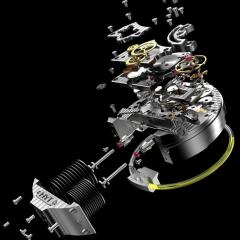
    • just one little minor reminder here this isn't your normal balance wheel.  pages 17 and 18 are what you really want to be looking at. normally studs don't turn but this watch has the etachron system designed for lots of adjustment. Personally I would try to rotate the stud back to where it's supposed to be. If you're lucky you didn't actually bend it at the stud it just looks really bad as the stud has been rotated grossly out of position.. I think things will look a lot better if you put the hairspring back where it's supposed to be by rotating the stud. it's hard to tell if you actually did bend it at the stud or not we won't know until you rotate the stud back more or less where it's supposed to be. Then you want to pay attention to the manual of how to put the hairspring back in the regulator pins because yes they rotate also and they rotated specific directions otherwise bad things will happen to your hairspring. so initially you can open up the regulator as wide as it can go and don't worry about closing it until thing everything is right then you can close them a little bit
×
×
  • Create New...