Jump to content

Recommended Posts

53 minutes ago, CWRNH said:

"0.1 Bypass caps on buffer stage lower pins"  Could you or anyone else please explain this to me?  I have everything done to this point and just need to know where these bypass caps connect....

Frankly, I am surprised the circuit works at all.  You have not provided a path for biasing the input stage of the LT1115.  You need a resistor from the non-inverting input to ground.  Pick a value to place the pole where you want to get your flat-band response.

Edited by LittleWatchShop
nin-<non
  • Like 1
Link to comment
Share on other sites

19 minutes ago, LittleWatchShop said:

Frankly, I am surprised the circuit works at all.  You have not provided a path for biasing the input stage of the LT1115.  You need a resistor from the non-inverting input to ground.  Pick a value to place the pole where you want to get your flat-band response.

Thank you!

Link to comment
Share on other sites

21 minutes ago, LittleWatchShop said:

Frankly, I am surprised the circuit works at all.  You have not provided a path for biasing the input stage of the LT1115.  You need a resistor from the non-inverting input to ground.  Pick a value to place the pole where you want to get your flat-band response.

Not my design, I am making a modified version of this.  What value should I start with for the Biasing of the input stage?  Sorry I am new to this...  Not totally incompetent but certainly don't have a through understanding at this point.  Any help is greatly appreciated.   Here is the PCB so far, based on the schematic.  Will modify it once I get a functioning board.image.png.43e5ec29563003cd129ee1a8beec1f21.png

  • Like 1
Link to comment
Share on other sites

29 minutes ago, CWRNH said:

Not my design, I am making a modified version of this.  What value should I start with for the Biasing of the input stage?  Sorry I am new to this...  Not totally incompetent but certainly don't have a through understanding at this point.  Any help is greatly appreciated.   Here is the PCB so far, based on the schematic.  Will modify it once I get a functioning board.image.png.43e5ec29563003cd129ee1a8beec1f21.png

Other than in the rail splitter, I do not see any bypass capacitors.  Poor practice.  You need to bypass every amplifier. 

For your input resistor, a 10k should work.

Link to comment
Share on other sites

Okay, I will put caps on pins 4 (V-) and ground on all amps and pins 7 (V+) and ground on all amps.   And will bias the main input with a 10k resistor between pin 2 (-) and ground of the first op amp.  Is this what you are talking about?   Again, thank you for your time.  I will post the updated board image when done.

  • Like 1
Link to comment
Share on other sites

13 minutes ago, JohnR725 said:

How do curiosity the modifications purpose is to achieve what?

I want to first get a decent working preamp setup.  Then refine it a bit and I want to add a UART output, among other things.  The preamp is only a small part of the project.  There are many different schematics and ideas, I have tried a few.  I am also trying to learn how all this stuff works, partly for curiosity sake and partly to build a machine that does some very specific things that I will explain later on as I am working them out.  I have several commercially made timing machines so this endeavor is more of a hobby at this point.   Electronics have always been an interest to me, I have finally gained some of the knowledge and equipment to pursue this hobby.  There are many projects that I have built and am planning on  building.  So....  I am, right now, trying to find a good quiet preamp.. LOL

Link to comment
Share on other sites

2 minutes ago, svorkoetter said:

What I find interesting is to ask questions about the circuit with only a circuit board layout instead of an actual schematic.


2 minutes ago, svorkoetter said:

What I find interesting is to ask questions about the circuit with only a circuit board layout instead of an actual schematic.

I simply wanted to know where HE (the person who made the schematic, that I created the layout from) was putting the bypass caps.  I can share my schematic too if you wish.  If I am asking something that is foolish I am sorry.  You don't know what you didn't know until you learn that you didn't know it.  This isn't rocket science but I don't have as much experience with electronics as you fine folks.  Sorry for any misunderstanding.

Link to comment
Share on other sites

1 hour ago, CWRNH said:

Okay, I will put caps on pins 4 (V-) and ground on all amps and pins 7 (V+) and ground on all amps.   And will bias the main input with a 10k resistor between pin 2 (-) and ground of the first op amp.  Is this what you are talking about?   Again, thank you for your time.  I will post the updated board image when done.

Yup!

  • Like 1
Link to comment
Share on other sites

Just now, LittleWatchShop said:

@cwrnh ...what layout tool are you using?  Looks like ExpressPCB.

Lately yes, Express.  I also have used Eagle but I am liking Express better.  I use Fusion 360 for most of my regular CAD/CAM nearly every day so I thought I would like Eagle but it is not as simple to use.  I used TINA do make the schematic and do some simulations.  Thankfully the tech school I teach at has a decent electronics department where I get some help.

Link to comment
Share on other sites

Join the conversation

You can post now and register later. If you have an account, sign in now to post with your account.
Note: Your post will require moderator approval before it will be visible.

Guest
Reply to this topic...

×   Pasted as rich text.   Restore formatting

  Only 75 emoji are allowed.

×   Your link has been automatically embedded.   Display as a link instead

×   Your previous content has been restored.   Clear editor

×   You cannot paste images directly. Upload or insert images from URL.


  • Similar Content

  • Recently Browsing

    • No registered users viewing this page.
  • Topics

  • Posts

    • Unfortunately I'm not that lucky. I started on the train side and after I noticed the binding I pulled everything out except the driving wheel to rule everything else out. It still binds. I'm going to double check that the pinion is fully seated on the staff first, then if no joy I'll push the bridge jewel up a fraction of a mm. Fingers crossed!
    • Happy to have helped, great way to start the day with a win! 🥳
    • Thank you for the advise!! It worked. The setting screw was a lock/unlock to remove the rotor. 
    • I have that French tech sheet too, it is a little different than the English one (eg, it doesn't have the auto works diagram). BTW, it looks like you are looking up the case number in the 1979 ABC supplement. The 1974 ABC catalog does have the 3093 case. As you determined it takes the 1222-5 crystal.  When I serviced my President 'A' (which also takes that crystal), I was able to fit a 29.8 crystal from my DPA crystal assortment. Those are, in my opinion, a great deal. The assortment comes with 10 sizes each from 27.8mm to 32.4mm in 0.2 increments. I pretty much use them for any non-armored crystal that takes a high dome crystal. I think they no longer make them but Cousins has still has some in stock but when I bought them they were around $40 for the set and now they are around $100. Still, at 40 cents a crystal it's still a good deal. For the large driving wheel, I remember I once assembled the keyless/motion works first and when I placed the large driving wheel it was interfering with the setting wheel on the dial side as the teeth were not fully meshing and it wouldn't fully seat. If that isn't the issue I got nothing and am looking forward to see how you solve it 🙂
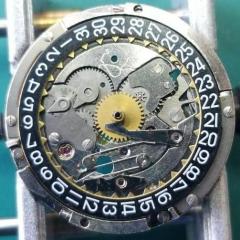
    • Not sure, but just looking at it, it seems like the screw on the right may be a fake? The one on the left may not be a screw in the regular sense at all, rather a 2 position device, I think you need to point the slot towards either of the 2 dots and one will secure and one will open. Like I said this is just my best guess looking at the pictures.
×
×
  • Create New...