Jump to content

Accutron 214 issues


Recommended Posts

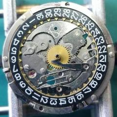
Hello everyone, I hope this finds you all well!  So a friend of mine picked up a non running Accutron 214 and asked me to have a look at it for him.  I’ve worked on a few in the past but this one is giving me some trouble.  The watch hums nicely but when I look at the indexing mechanisms something seems a little off.  I’ve been going through Henry Frystak’s tutorials about indexing and also have compared it to some of my personal Accutrons and something doesn’t look right.  The jewels are extremely close to each other compared to watches I have and videos I’ve watched.  Also, the springs, if possible seem long?  In Frystak’s videos he mentions that both springs should have a slight bend in them when not in contact with the index wheel, but be flat when in contact with it.  If these springs would be flat they would be really high on the wheel.  From what you see in the picture, is this something that can still be adjusted or is something else going on here?  Any and all help would be greatly appreciated!

F45FC79C-69EC-4D02-940E-27374B24307C.png

Link to comment
Share on other sites

you really should have the 214 service manual.

I think both fingers need to be straightened out and the stress limiter is definitely not where it's supposed to be. I'm snipping an image out of the service manual

14 minutes ago, Stevelp said:

So a friend of mine picked up a non running Accutron 214

do you think somebody is played with it before you? Then yes obviously that's a stupid question if you look at the fingers but?

15 minutes ago, Stevelp said:

springs would be flat they would be really high on the wheel.

I'm attaching another image and you see the missing another stress limiter? At least compared to this picture.

II don't think they can change the index wheel to something of the different sides it's not like they came in different sizes.

as you have nothing to lose I'd go ahead and straighten the fingers out and see just how bad they're going to be if they're too high then you're going to have to replace them and of course as you know the fingers are not separate replaceable.

214 stress limiter position.JPG

214 photo fingers.JPG

Link to comment
Share on other sites

Hi JohnR725, thanks so much for the quick response!  I do have the service manual and service test set for the accutrons.  I did check with him and he’s unaware of the history of it but I agree it sure looks like someone has been in there before!  Yes there is one stress limiter missing and the other is bent below the spring.  Agreed, I’ll straighten everything out and see where that gets me.

Link to comment
Share on other sites

Funnily enough, a few weeks ago I got one of the Omega F300, similar to yours. 

I read everything I could about them, which on the Internet is loads of papers and articles. 

The main things o got out of it, apart from that you need a microscope is don't touch the escape wheel, I made a good job serviced the watch, but without the microscope I couldn't do it. 

Good luck. 

My post about the watch is on the forum somewhere. 

Edited by antonyh
Link to comment
Share on other sites

  • 2 weeks later...

Hi everyone, so a quick update.  I had some time to poke away at this watch over the last few days.  I did end up straightening out the fingers and getting it running but not for very long and things quit working again.  I adjusted everything as per the manual but still no go.  The wheel will stop and run for half a turn and so on.  I had a really close look at the index pawl bridge with microscope and noticed this.  It looks as though there is glue holding the finger in place and the stress limiter is missing. So who knows what’s all gone on here.  I sourced a new bridge so I should have it shortly.  

BBB0C102-3758-4FC3-B5FA-B31DDC4A6831.png

Link to comment
Share on other sites

2 hours ago, Stevelp said:

I adjusted everything as per the manual but still no go

I think based upon the original description and the photograph definitely replace anything that looks suspicious. These are not the kind of watches were things can be sort of right they have to be absolutely perfectly right or you're not going get it to run

Then adjusting as per the manual you might want to look at the link below. Basically adjust everything physically like the manual did but the phasing procedure is changed a little bit for use with modern batteries.

http://members.iinet.net.au/~fotoplot/accphs.htm


Link to comment
Share on other sites

  • 3 weeks later...

Hi everyone!  Sorry for the long absence from this post, available time for this project hasn’t been abundant lately.  Everything is all back together after swapping out the pawl bridge and tuning fork with ones from a donor movement.  The fingers for the index and pawl jewels are now nice and straight.  The watch does. Is fun but then falls into a pattern of stopping and starting every second.  When watching the index wheel it seems to stop in the same spot on the wheel every rotation.  I’m thinking it’s pretty safe to assume that the index wheel has a dead spot?  

Link to comment
Share on other sites

2 hours ago, Stevelp said:

I’m thinking it’s pretty safe to assume that the index wheel has a dead spot?  

another way to test the index wheel is with no power pluck the fork. This will cause the index wheel to spin for a little bit and then when it comes to stop make a mental note of where the arms appear to be. Repeat a couple of times and see if the index wheel always stops in the same place of it does it's a bad wheel.

Link to comment
Share on other sites

  • 3 weeks later...

Hello everyone, a final update!  Thanks JohnR725 and HSL again for some great information!  JohnR725 I put your suggestion into practice and sure enough there was a dead spot on the index wheel.  After replacing the wheel and making all the adjustments to the index mechanism described in the manual away it went!  I've learned a lot of very useful tips and information working with this watch and from the answers to my questions from the forum members.  Thanks everyone for your help!

Link to comment
Share on other sites


  • Recently Browsing

    • No registered users viewing this page.
  • Topics

  • Posts

    • Unfortunately I'm not that lucky. I started on the train side and after I noticed the binding I pulled everything out except the driving wheel to rule everything else out. It still binds. I'm going to double check that the pinion is fully seated on the staff first, then if no joy I'll push the bridge jewel up a fraction of a mm. Fingers crossed!
    • Happy to have helped, great way to start the day with a win! 🥳
    • Thank you for the advise!! It worked. The setting screw was a lock/unlock to remove the rotor. 
    • I have that French tech sheet too, it is a little different than the English one (eg, it doesn't have the auto works diagram). BTW, it looks like you are looking up the case number in the 1979 ABC supplement. The 1974 ABC catalog does have the 3093 case. As you determined it takes the 1222-5 crystal.  When I serviced my President 'A' (which also takes that crystal), I was able to fit a 29.8 crystal from my DPA crystal assortment. Those are, in my opinion, a great deal. The assortment comes with 10 sizes each from 27.8mm to 32.4mm in 0.2 increments. I pretty much use them for any non-armored crystal that takes a high dome crystal. I think they no longer make them but Cousins has still has some in stock but when I bought them they were around $40 for the set and now they are around $100. Still, at 40 cents a crystal it's still a good deal. For the large driving wheel, I remember I once assembled the keyless/motion works first and when I placed the large driving wheel it was interfering with the setting wheel on the dial side as the teeth were not fully meshing and it wouldn't fully seat. If that isn't the issue I got nothing and am looking forward to see how you solve it 🙂
    • Not sure, but just looking at it, it seems like the screw on the right may be a fake? The one on the left may not be a screw in the regular sense at all, rather a 2 position device, I think you need to point the slot towards either of the 2 dots and one will secure and one will open. Like I said this is just my best guess looking at the pictures.
×
×
  • Create New...