Jump to content

A.scild 1906 train


Recommended Posts

hey guys.

I cannot work out how this train works.

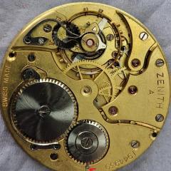
See pic 3  Wheel numbered 1 is the seconds hand wheel it is turned by the mainspring barrel.

Then wheel 1 turns wheel 3 

Wheel 3 looks like it is meant to turn wheel 2 but it isnt.

Wheel 2 i have been told has the of center canon pinion on iy that goes through a hole to the rear of the plate.

And wheel 1 is turning the escape wheel.

When i turn wheel 1 buy hand it turns wheel 3 and the escape wheel,

Wheel 2 does not move.

But if i then turn the mainspring barrel number 2 wheel make a attempt to start.

So to me the mainspring seems to power wheel 1 and 2 seperately and wheel 1 turns wheel 3 and the escape wheel.

This does not seem correct to me and its driving me insane.

any advice or walkthroughs would be gratefully appreciated.

cheers

gary


IMG_20210501_195020.jpg

IMG_20210501_195027.jpg

IMG_20210501_195216.jpg

Link to comment
Share on other sites

Hi there ,The center wheel drives the pinion of the third wheel, and the third wheel drives the pinion of the fourth wheel. Rearrange the wheels until you get this happening. Then put the bridge on and have a look .It can be a bit of a false reading without the bridge as the wheels jump around and lean into other wheels  where they shouldn't  if you try to test them without them in their pivots 

hope this helps


  • Like 1
Link to comment
Share on other sites

notice at the link below something that going to quote here "indirectly driven minute allows a big balance and low profile" this means you do not have your normal center wheel that's driven by the mainspring barrel.

This means your numbers don't quite work out right. The fourth wheel drives the escape wheel which is basically the fourth wheel is number one in the drawing escape wheel is number four

number two is being driven by the mainspring barrel and that would normally be the center wheel but that is somewhere else we need the other side of the movement to see that. Then if I'm interpreting everything correctly number three is the third wheel.

It's a problem with indirect things. The wheels actually look right as they are now they just numbered wrong see if you put the bridge on top do they turn? If they don't turn then you get to rearrange the wheels but they look right. Then the picture the dial side of course so we can see how that's arranged.


http://www.ranfft.de/cgi-bin/bidfun-db.cgi?10&ranfft&0&2uswk&AS_1906

Link to comment
Share on other sites

hi @gary17 I think I have a very similar question about a movement in the same family, an AS2066. I'll post some pictures here of the wheels. To me, if you're configuration is the same as mine, it looks like the barrel powers the 2nd wheel (also called the great wheel by AS) that is the one that wedges down against the teeth on the barrel. I've asked the group for confirmation of this but no one has responded yet so I can't promise I'm right on that. It's been referred to as movement with an offset cannon pinion. Anyway, the second wheel then powers the third, which has teeth on top to power the fourth wheel (center wheel). I'm not sure which of these is powering the escape wheel. Check to make sure you have the crown pushed in. It may be that if your crown is pulled out to setting position that the second wheel will not move as designed

My problem is that when I have all the wheels in and push the barrel I see the staff of the 2nd wheel spin in its bushing but the train of wheels does not move. Conversely, I can push on the center wheel or the 2nd wheel and the train of wheels spins freely. I'm just having trouble with engagement between the barrel and train. I've attached pics of the escape wheel, center wheel, 3rd wheel, 2nd wheel and then the dial side with the 2nd wheel in place.

IMG_5151.jpg

IMG_5150.jpg

IMG_5149.jpg

IMG_5147 (1).jpg

IMG_5153.jpg

Edited by Rowbear23
Link to comment
Share on other sites

Hey

I now have power through the second wheel through the plate that is turning the canon pinion. But alas no movement from the train. I can move the train by hand and they all turn. but i am damned if i can work out were the power come to them from. I know it has to be the mainspring barrel???

cheers

gary

Edited by gary17
Link to comment
Share on other sites

you tried moving the crown/stem to make sure it isn't in the setting position? Also, stare at the pinion on your 2nd wheel under a loupe while you push on the barrel, can you tell if that pinion is rotating but the wheel is not? That's what I'm getting in my 2066.

Link to comment
Share on other sites

Hey gary, if it's the same problem I was having, you see the pinion move in the bushing but the wheel doesn't spin, then here is how I solved that problem tonight. Maybe you figured this out already, but I took the 2nd wheel/great wheel out, put it in my staking tool and did a couple light taps to get the wheel tightened on the staff. That seemed to do the trick. I did a dry fit, pushed the barrel and all wheels in the train spun like they are supposed to. The barrel is definitely powering the 2nd wheel and then the second wheel carries that power to the 3rd, etc. 

Link to comment
Share on other sites

Hey rowbear.

Thanks. I now have a fully functioning as 1906 movement. I put my wheel in small vice and used trusty hammer to achieve what you did with staking tool.

Much appreciated.

cheers

gary

  • Like 1
Link to comment
Share on other sites

I'm guessing part of it has to do with the fact that it is wedged in there a bit beside the mainspring barrel. If someone removes it before removing the barrel then they may be putting pressure on that wheel if they grip it with their tweezers and pull up since the barrel partially obstructs removal. 

Link to comment
Share on other sites


  • Recently Browsing

    • No registered users viewing this page.
  • Topics

  • Posts

    • Thank you to both of you!  I've been somewhat derailed by this quandary for a couple of days now. I am guessing that the point of the wider tweezers is to support the whole spring at the same time in an effort to prevent it going under tension... I have already discovered the Zen of a clutter free space, and trying to keep my work well away from the edge, however the most terrifying of the flights wasn't so short, I had my work in the middle of the table and nothing else around.  That particular launch was towards me.  I distinctly recall feeling the spring hit my left hand as it escaped.  I only found it by dumb luck, on the floor, between the legs of my chair.  I need to order a pack of replacements just in case.  I think I recall a thread discussing where to find them, and the differences between the clones and the authentic ETA ones, pointing out that they're not interchangeable (the clones being longer IIRC).  Now I just have to find that thread again.  What I haven't mastered is the zen of the search function here.  I'm sure I"ll get that down eventually. So this is similar to, but different from one of the posts I had found in my original searches (or maybe I'm just hallucinating, I can't find the post I thought I remember).  The bits about the corner filled in a gap in what I'd read before.  At least I have a more clear picture in my head about what needs to happen now.  Yes, I've learned about how touchy these springs are.  What I'm not sure I have a good grasp on is the understanding of what causes the spring to flex, other than to say "the slightest little touch"  I think I'm going to try a small bit of Rodico to position the spring next time.
    • I think it's stamped on the inside cover. 309 I think.
    • Hi all, needing a little help. I have an old Casio AQ-321G, but have no idea what battery it takes. I've looked around online, but cannot see anything... I see a 309 stamped on the case back, could this be it....? Can you please help, below are some pictures:
    • The radial teeth are for hte seconds register, and the other (which is simple and doesn' take away significant torque from the train) for the minutes register.
    • The original 6139A manual is very clear in how to disassemble and how to assemble ...... step-by-step. However I haven't seen the 3169B manual, even in the Japanese version around, which clearly highlights the difference in center-wheel.   6139A Seiko Technical Guide.pdf 6139_A.pdf 6139A.pdf 6139b.pdf 6139B repair guide jp.pdf        
×
×
  • Create New...