Jump to content

Repinning stud advice?


Recommended Posts

Hi all,

I am working on a cute Pobeda for my significant other. It was running great, but after taking the balance on and off a few times, the hairspring stud has come loose. The pin just appears to have backed out of its hole - the hairspring is vertical but the stud is flopping around all over the place.

My basic plan is to, under a microscope, hold the stud upright, and push the pin back in using hairspring tweezers or an oiler. Any advice about tools or methods? Seems straightforward but obviously there is much that can go wrong here. Pivots are good and I already reshaped the overcoil, so I'd rather not junk this balance. Thanks.

Link to comment
Share on other sites

Normally this is done with a studding table, which is a tool that clamps the stud at whatever height you want so you can clamp it with the hole sticking out at table height. Slide the spring in, then insert pin.


Most folks don't have that tool, so the next best thing is the cock itself. Fix the stud in place, insert spring, then pin. To press the pin tight it's very useful to modify a pair of tweezers by removing about 0.25mm from the end of one side; now you can rest against one side of the stud with the short end and squeeze the pin in with the other side.

  • Like 2
  • Thanks 1
Link to comment
Share on other sites

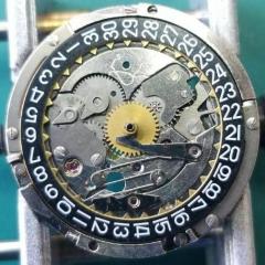
Thanks guys for your resposes. @Nucejoe, the movement is a Zim 2602 with a fixed stud. Here are some pictures of the balance and stud itself. As you can see, the stud hasn't come off - it's just flopping around all over the place. I can flip the stud to lean the other direction and take the same picture. Do you guys advise removing the pin and starting from scratch, or just trying to push the pin back in? And yes, I know the pin looks super weird and rough here.

IMG_20210304_081447506.jpg

IMG_20210304_081416409.jpg

Edited by JohnC
Link to comment
Share on other sites

Hi JohnC,

Doesn't look it would creat any noticable beat error, which is a pain to adjust with fixed stud holders.

In case you feel no master re-pin ner, I refit the stud with the cock, put em back on the mainplate and just use a bit of epoxy 5 to keep the hairspring in place. 

Good luck.

  • Thanks 1
Link to comment
Share on other sites


  • Recently Browsing

    • No registered users viewing this page.
  • Topics

  • Posts

    • Unfortunately I'm not that lucky. I started on the train side and after I noticed the binding I pulled everything out except the driving wheel to rule everything else out. It still binds. I'm going to double check that the pinion is fully seated on the staff first, then if no joy I'll push the bridge jewel up a fraction of a mm. Fingers crossed!
    • Happy to have helped, great way to start the day with a win! 🥳
    • Thank you for the advise!! It worked. The setting screw was a lock/unlock to remove the rotor. 
    • I have that French tech sheet too, it is a little different than the English one (eg, it doesn't have the auto works diagram). BTW, it looks like you are looking up the case number in the 1979 ABC supplement. The 1974 ABC catalog does have the 3093 case. As you determined it takes the 1222-5 crystal.  When I serviced my President 'A' (which also takes that crystal), I was able to fit a 29.8 crystal from my DPA crystal assortment. Those are, in my opinion, a great deal. The assortment comes with 10 sizes each from 27.8mm to 32.4mm in 0.2 increments. I pretty much use them for any non-armored crystal that takes a high dome crystal. I think they no longer make them but Cousins has still has some in stock but when I bought them they were around $40 for the set and now they are around $100. Still, at 40 cents a crystal it's still a good deal. For the large driving wheel, I remember I once assembled the keyless/motion works first and when I placed the large driving wheel it was interfering with the setting wheel on the dial side as the teeth were not fully meshing and it wouldn't fully seat. If that isn't the issue I got nothing and am looking forward to see how you solve it 🙂
    • Not sure, but just looking at it, it seems like the screw on the right may be a fake? The one on the left may not be a screw in the regular sense at all, rather a 2 position device, I think you need to point the slot towards either of the 2 dots and one will secure and one will open. Like I said this is just my best guess looking at the pictures.
×
×
  • Create New...