Jump to content

Identifying clock


MechanicMike

Recommended Posts

Letter from Joe Collins, 

Thanks for inquiring about my mainspring winder. I do not make the Winder any longer. Here are the Plans

I do not supply the sleeves for capturing barreled springs. These can be bought at Merritts Antiques for about $40 US. (9 piece, Ollie Baker type) They can also be found at TimeSavers and other materials outlets.

A video of the winder in use can be found here: 
http://www.youtube.com/watch?v=6uOsZ_ZIvLc

Thanks again for the inquiry,
Joe Collins  
Email: [email protected]

@@@@@@@@@


Update from Al,
Here is a gentleman that built a winder that explains what he chose to do. I do not like his copper clamps for the barrel, they may scratch the barrel. But if lined with leather or made of wood is another way to accomplish the task.
Use a Tap handle which has a 4 jaw chuck to grip the four sided mainspring arbor.
https://www.youtube.com/watch?v=S5XxM5PwSNM&t=149s

And another variation on a theme using mechanics tools.
https://www.youtube.com/watch?v=Qczmx8I1zzI
He also shows the purchased components from stores.

There are many other YouTube video's in case you want to browse other clockmakers solution to a problem.
Clock repair supply houses:
Merritts.com
Timesavers.com
 

  • Like 1
  • Thanks 1
Link to comment
Share on other sites

  • 2 weeks later...

Latest on the 1950 Kundo

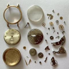
Hi everyone-I've wracked my brain and I need assistance. Pretty simple re-assembly you would think but sure enough, the gods of horology want to play games today so it's not cooperating, and after several attempts and looking all over, the center wheel and 3rd wheel seem to be binding up and the whole thing won't fall into place. What am I missing?  The first series of pics shows the train and where the 3rd n 4th wheel are touching, locking up there. Next is the hour wheel, intermediate wheel, washers, lock washer, hand tension washer and hand lock pin, as they sat when I disassembled.  The last 3 pics are time of disassembly, which I'm attempting to do just in reverse order.  My suspicion lies with the washers or maybe a wayward spacer that pinged that I missed? Or a round peg in a square hole? The 400 day bible gives nothing except a nice parts page. I know I bet it's right in front of me but I need a fresh set of eyes. Thanks people I'll check back in awhile. Happy Sunday.

MM

20210124_115410.jpg

20210124_115520.jpg

20210124_115734.jpg

20210103_042605.jpg

20210103_035056.jpg

20210103_034553.jpg

Link to comment
Share on other sites

On 1/12/2021 at 5:22 AM, watchweasol said:

Hi Mike  If you can get one of these tools it makes the escapement easier to adjust, nt cheap  the one pictured is from cousins at £27  you can get them cheaper though.

t5058_pic2_cmyk1.jpg

Hi WW I read somewhere that a needle nose pliers does the same. Is that true? Otherwise I have this on my radar

Link to comment
Share on other sites

Hi Mike    needle noses will work ok but you don't have the same control, with the tool its micrometer adjustment . If you are going to use needle nose pliers stick somthing over the serrations or file them smooth. Or alternativly make a tool with a slot in it to fit the upper spring block with a longish handle.

As far as the wheels are concerned the center wheel that carries the hour wheel etc will have hole in it for the pin to hold the hands on so put that bit through the front plate first and start from there fitting the other wheels as you go. once the back plate is on check the rotation of the wheels and then fit the anchor/pallet. once done then reassemble the wheels on the front plate 

  • Thanks 1
Link to comment
Share on other sites

On 1/12/2021 at 5:22 AM, watchweasol said:

Hi Mike  If you can get one of these tools it makes the escapement easier to adjust, nt cheap  the one pictured is from cousins at £27  you can get them cheaper though.

t5058_pic2_cmyk1.jpg

Happy to report, one is on the way. Getting new toys is part of the fun?

  • Like 1
Link to comment
Share on other sites

9 hours ago, HectorLooi said:

I think you got the 4th wheel upside down. If you look at the original photo you posted, the wheel should be the other way round.


On 1/12/2021 at 6:19 AM, watchweasol said:

IT certainly is  I did in the past use jewelers pliers with fine jaws but the control was not good with this tool you can get micrometer adjustment, would use nothing else to adjust these clocks.


9 hours ago, HectorLooi said:

I think you got the 4th wheel upside down. If you look at the original photo you posted, the wheel should be the other way round.

see pics next post. 

Link to comment
Share on other sites

Hector, Weasol(you mind being called Weasol? always feel weird about that lol)and Hippy:

got back from clearing out the latest snow storm and I took some better pics. I don't think I have the center wheel backwards, as the first pic might be deceiving. it can only go in one way because of the hole for the hand tension washer and pin, and the larger pivot hole size, and the long end to accommodate the hour wheel and cannon pinion, shown with red arrows in 1st 2nd and 3rd pics. 4th pic in red and orange shows where the wheels are impinging on each other and 5th pic shows train arrangement with regard to center/4th wheel and 3rd wheel. so yes, Weasol that's where I originally started was off the hand tension pin hole on center/4th wheel and went from there and ran into the wheels upsetting the apple cart. maybe was this clock assembled wrong by a previous repairman and got the washers wrong or a spacer missing unbeknownst to me? I have zero history on this one only that it's a family heirloom and hasn't worked in over 40 years. 

tell you guys one thing-my coloring book and crayon skills are becoming sharp.

266662501_400dayclockhandtensionpinhole.thumb.jpg.74ba65f3e040b5d7bddd1d9657998376.jpg1204405339_400dayclockhourwheelcannonpinion.thumb.jpg.04a0eee0d60ac764aa32d3e38f15118d.jpg525015354_400dayclockcenter4thwheelpivot.thumb.jpg.3972bfec696bbe81bba6f37442b0078e.jpg525015354_400dayclockcenter4thwheelpivot.thumb.jpg.3972bfec696bbe81bba6f37442b0078e.jpg1852516365_400dayclockgeartrainimpingment.thumb.jpg.c4d19c785871cb133435e64bab34b06b.jpg1852516365_400dayclockgeartrainimpingment.thumb.jpg.c4d19c785871cb133435e64bab34b06b.jpg494445512_400dayclocktrainimpingementtopview.thumb.jpg.840999b0d0e1595a592ae19ff84a419c.jpg here I come...

I love this stuff...

Link to comment
Share on other sites

post script: the view of the larger pivot, red arrow, is where I suspect a spacer, or the two washers that were directly behind the cannon pinion might go, to provide clearance between the two wheels. but I don't know. anyone want to loan me their 1950 Kundo 400 day clock for a reverse engineering study with me? ??

Link to comment
Share on other sites

if you look at your original post, the 3rd photo shows that not all the wheels are clustered against the front plate. One of them is reversed with the wheel against the back plate. As a general rule, the gears are always arranged with the wheel to pinion, wheel to pinion. I think that wheel upside down.

There might be some confusion here. We are not talking about the centre wheel. The going barrel is counted as the 1st wheel or sometimes called the great wheel. So the 4th wheel we are referring to is the one before the centre wheel.

  • Thanks 1
Link to comment
Share on other sites

6 hours ago, HectorLooi said:

if you look at your original post, the 3rd photo shows that not all the wheels are clustered against the front plate. One of them is reversed with the wheel against the back plate. As a general rule, the gears are always arranged with the wheel to pinion, wheel to pinion. I think that wheel upside down.

There might be some confusion here. We are not talking about the centre wheel. The going barrel is counted as the 1st wheel or sometimes called the great wheel. So the 4th wheel we are referring to is the one before the centre wheel.

Aha! Ok that might explain it-we were talking about two different things. Counting the barrel. Ok I'll be back at it when I get home later today and let you know. Many thanks Hector.

Link to comment
Share on other sites

1 minute ago, watchweasol said:

Hi Mike  I have attached two pics of my Kundo miniture hope they provide enough Information. On way is to look at the wheel and pinion sizes the largest near the barrel and get finer to the escapement, not always fool proof but a good guide.

DSCF3505.JPG

DSCF3504.JPG

Combining this with what Hector has said, I  will be checking as soon as I get home later and follow up.  Thanks Weasol. 

Link to comment
Share on other sites

18 hours ago, HectorLooi said:

if you look at your original post, the 3rd photo shows that not all the wheels are clustered against the front plate

Bingo! Hector you nailed it! I had gotten so flustered I didn't see it so I went back to the very beginning and looked at the 3rd shot as you said and there it was...well done sir. well done. Thank you very much! if i never get this thing to run again, I'll still be happy I got restored back on track. whew.

Link to comment
Share on other sites

12 hours ago, watchweasol said:

Hi Mike  I have attached two pics of my Kundo miniture hope they provide enough Information. On way is to look at the wheel and pinion sizes the largest near the barrel and get finer to the escapement, not always fool proof but a good guide.

DSCF3505.JPG

DSCF3504.JPG

yep, Hector and Hippy nailed it, and I confirmed and compared to your pics. Except now, i'm wondering, "How the heck does he get his stuff so clean and shiny?"??

thanks Weasol!

Link to comment
Share on other sites

Join the conversation

You can post now and register later. If you have an account, sign in now to post with your account.
Note: Your post will require moderator approval before it will be visible.

Guest
Reply to this topic...

×   Pasted as rich text.   Restore formatting

  Only 75 emoji are allowed.

×   Your link has been automatically embedded.   Display as a link instead

×   Your previous content has been restored.   Clear editor

×   You cannot paste images directly. Upload or insert images from URL.


  • Recently Browsing

    • No registered users viewing this page.
  • Topics

  • Posts

    • Thank you so much, Hector and CJ. I appreciate the tech sheet and the video. Gasp, I think I will make the attempt. What's the worst that can happen? I think there may be a new balance complete in my future, though.  I'll update the post and let you know the result. R, Frank  
    • So here is the new base (v 2.1), I made it so that the base will fit over and swallow the stump of the hand pusher tool (or at least my clone of the tool), I also reduced the OD of the bottom skirt a little as it looked/felt a little large, here are a few pictures and the fake .pdf file which you need to convert to .zip once downloaded.   The cut-out seen on the below image on the bottom of the base should swallow the OD (40 mm, +0.1 mm tolerance) of the stump and the height of the stump 9.5mm (measured to 9.1mm, but rounded to 9.5mm) - let me know if this works for your tool.   Note, I think you may need to print supports for the new internal shelf created? Here is the fake .pdf for just the FreeCAD base file and 3mf files Modular Movement Holder.pdf Here is the fake pdf for complete set of the new base and ring FreeCAD/3mf files: Modular Movement Holder base and ring v 2.1.pdf However, I'm wondering how often you could use this feature, adding the dial usually increases the OD of the movement, so you would need a new (larger) adapter ring tuned to the OD of the dial and I wouldn't like to grip the dial in any kind of movement holder if It could be avoided for fear of damaging it. Maybe I'm misunderstanding you?
    • Hi Frank, you have dived headlong into the deep end. Hairspring work has to be the scariest thing a newbie has to tackle. Your hairspring appears to be bent and just putting it back into the regulator would not allow the balance to work properly. It might start oscillating but the performance would not be good. The proper thing to do is to unstud the hairspring, remove the hairspring from the balance, reinstall the hairspring on the stud carrier, reshape the endcurve and centre the collet to the balance jewel hole. This challenge would either make you or break you. Hope that you will be able to fix your watch. Welcome to the world of watchmaking.  Watch this video. It think it'll give you an idea of the task ahead. From your 1st photo, I think you have a etachron type stud. Let me see if I can find a video on how to remove it from the arm.
    • Have read of the Tech Sheet attached on the balance section page 12. It may be bent but until you reposition it back in the regulator pins you'll never know. Cheers CJ 4R35B_4R36A.pdf
    • Aloha All, My Seiko 4R35B movement stopped working today. Upon closer inspection, it looks like the balance spring came out of the regulator pin. This is my first time working on a balance. Any advice on how to get this spring repositioned (back to normal)? I'm pretty sure that while adjusting the beat error on this movement, I must have turned the stud (I didn't even know they turned), and the spring eventually fell out.  Will the spring go back to even spacing when it's back in the pin, or does it look bent? Thanks, Frank  
×
×
  • Create New...