Jump to content

Eta 2512-1 Movement


Recommended Posts

This is probably the smallest movement I've worked on & the 4039 holder that arrived yesterday rather dwarfs it! (Btw, I tried the carbon fibre version which was £1 dearer than the steel but it is quite nice.)

Official ETA diameter is 17.2mm.

post-687-0-55391700-1424560535_thumb.jpg

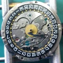
Here the dial has been removed & next the minute train bridge & minute wheel/setting wheel:

post-687-0-83618300-1424560638_thumb.jpg

Incidentally, the minute wheel is driven independently by the third wheel - you can see it's jewel at 8 o'clock in the middle.

The barrel, train & pallet bridges are nicely plated rather than plain steel & is signed:

post-687-0-72185500-1424560929_thumb.jpg

post-687-0-88627500-1424560961_thumb.jpg

The large parts are soaking in solvent overnight....lets hope I can get it back together tomorrow!

Link to comment
Share on other sites

  • 3 years later...

Old Topic, but I am working on a 2512-1 right now.  Somehow, I failed to note where/how the intermediate wheel lower pivot seats.  I feel I am missing something, but my pictures taken upon dis-assembly do not show the lower pivot point for this wheel.  It is the wheel overriding the barrel in the picture.  Advice please!


Thanks,


RMD

IMG_20190112_145438172.jpg

Edited by rduckwor
Link to comment
Share on other sites

Never mind.  I found it.  Strangely there is a non-jeweled bearing press fit into the main plate below and just off the edge of the MS barrel.  Teeny, tiny.  I overlooked it the first time thru.  Getting the pivot into that tiny hole with the other wheels and barrel in place was a test of patience.  Its done and the train runs!!  Whew!!


RMD

Link to comment
Share on other sites

  • 3 years later...

I am aware of the age of this thread.

I just got through servicing a predecessor to the 2512-1, the 2512.  I too was sort of baffled when I looked for the lower pivot for that wheel. And yes, it is a bit of a bear to situate. Fortunately, I had honed my chops on such things by working on some Accutrons recently and dealing with their index wheels.

The only issue I'm having is that the watch still has hangups at the click. I'm pretty sure that a little lubricant under the rather unconventional click will fix it up. Cheers.


Link to comment
Share on other sites

1 hour ago, MrRoundel said:

I am aware of the age of this thread.

I just got through servicing a predecessor to the 2512-1, the 2512.  I too was sort of baffled when I looked for the lower pivot for that wheel. And yes, it is a bit of a bear to situate. Fortunately, I had honed my chops on such things by working on some Accutrons recently and dealing with their index wheels.

The only issue I'm having is that the watch still has hangups at the click. I'm pretty sure that a little lubricant under the rather unconventional click will fix it up. Cheers.


When releasing the mainspring power via the combined click and spring, it can be quite easy to bend the combined click and spring out of shape. The combined click and spring will then not hold the ratchet wheel properly. You may have to bend it slightly so that it engages the ratchet wheel properly.

Link to comment
Share on other sites

The ETA 2512 doesn't have the, what I see as improved, one-piece spring/click combination. It has a relatively low tension spring that interacts with a click that has small nubs on the bottom of the click-arm that protrude into holes in the plate.

I'm still fighting with this thing. The spring goes out of position with the slightest movement of the click while trying to situate the ratchet wheel. It's maddening, to be sure. I'm about to buy a new spring in the hopes that it will hold better. Truth be told, the existing one looks fine, but it has a hair trigger. Cheers.


8B5DE13B-4195-4CF7-91E4-5506D8E734DF.jpeg

Link to comment
Share on other sites

Join the conversation

You can post now and register later. If you have an account, sign in now to post with your account.
Note: Your post will require moderator approval before it will be visible.

Guest
Reply to this topic...

×   Pasted as rich text.   Restore formatting

  Only 75 emoji are allowed.

×   Your link has been automatically embedded.   Display as a link instead

×   Your previous content has been restored.   Clear editor

×   You cannot paste images directly. Upload or insert images from URL.


  • Recently Browsing

    • No registered users viewing this page.
  • Topics

  • Posts

    • Thank you for the advise!! It worked. The setting screw was a lock/unlock to remove the rotor. 
    • I have that French tech sheet too, it is a little different than the English one (eg, it doesn't have the auto works diagram). BTW, it looks like you are looking up the case number in the 1979 ABC supplement. The 1974 ABC catalog does have the 3093 case. As you determined it takes the 1222-5 crystal.  When I serviced my President 'A' (which also takes that crystal), I was able to fit a 29.8 crystal from my DPA crystal assortment. Those are, in my opinion, a great deal. The assortment comes with 10 sizes each from 27.8mm to 32.4mm in 0.2 increments. I pretty much use them for any non-armored crystal that takes a high dome crystal. I think they no longer make them but Cousins has still has some in stock but when I bought them they were around $40 for the set and now they are around $100. Still, at 40 cents a crystal it's still a good deal. For the large driving wheel, I remember I once assembled the keyless/motion works first and when I placed the large driving wheel it was interfering with the setting wheel on the dial side as the teeth were not fully meshing and it wouldn't fully seat. If that isn't the issue I got nothing and am looking forward to see how you solve it 🙂
    • Not sure, but just looking at it, it seems like the screw on the right may be a fake? The one on the left may not be a screw in the regular sense at all, rather a 2 position device, I think you need to point the slot towards either of the 2 dots and one will secure and one will open. Like I said this is just my best guess looking at the pictures.
    • Hi! I am in the process of restoring a rado captain cook mkII. I want to remove the rotor, but I am not sure how to and need some help. As you can hopefully see on the photo there are 2 screws. The left one has two positions, the right one looks like a regular screw. I have tried turning the right one, but it does not give even after using more force than I would expect. Anyone know the function of the left screw with the two positions and how to remove the rotor? Thanks!!
    • Welcome to the group Stirky. You can search for just about every subject in the craft here. Don't be afraid to ask if you can't find the answer that may have already been covered ( some ad nauseum LOL ). You don't have to buy Bergeon to get good quality. There are many decent mid-range tools available that will last you a lifetime. Cousins would be a good place to start . Cheers from across the pond ! Randy
×
×
  • Create New...