Jump to content

Do or Die repair


Recommended Posts

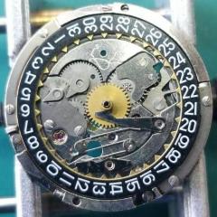
Zero chance of getting a spare part, so either a new movement or take the power reserve function from the watch. This is an intermediate  wheel assembly from the  power reserve train, which had one of the wheels in the assembly with 3 missing teeth. With nothing to lose,  I have decided to have a stab at a repair. Next stage is to clean up, put the little sub assembly back together and then try it in the watch. I have no idea if it is going to work!!!

BTW, just to explain. The wheel with a section cut out is a doner from my spares bin which had the closet tooth profile. I cut a section of 3 teeth and implanted (soldered) it into the damaged wheel. 

925B61DA-31A4-4BA4-B80C-D637B705F216.jpeg

60297377-CE7C-4B08-BA6E-BB5A46802D70.jpeg

2A0CB19D-687C-405E-80E8-B69F5ECDBE03.jpeg

A711DE05-3B33-41FD-AF45-76A30560552B.jpeg

  • Like 1
Link to comment
Share on other sites

Looks good. Did you try “topping” the repaired wheel, ie. checking if the new teeth are relatively proud of the original teeth and stoning down?

Must have been a really tricky job at that size!

Link to comment
Share on other sites

A good try. I have blown the photo up to take a look, the teeth are too high and you have the wrong angle each side, it will be hard for the teeth to mesh when it makes contact with other teeth. I think it will jam up. 

60297377-CE7C-4B08-BA6E-BB5A46802D70.thumb.jpeg.ec8cde35aba335838695c9b202c819ca.jpg

Link to comment
Share on other sites

I think @oldhippy is right.
 

From wrestling with hairsprings this is one of the trickiest repairs to do, and when doing it one whish one saved the previous discarded part in the “good to have in the future box”.
When it comes to replacing the teeth the donor piece has to come from a wheel not only with the same diameter but also the same type of teeth and depth on them, this is so you will get the correct amount of freedom for the wheels to rotate in a correct way.

Even small differences like these ones will make the wheels not to run correctly in the length.

 1743899632_Damagedteeth.jpg.fced3b43e64ec92047d365def705b56b.jpg

Another thing to consider is how to put the new piece in place. One should avoid making a rectangular shape to fit with and instead make a “dove tail” shape with a precision triangular file.

Since the teeth on the wheel is subjected to lateral driving pressures a rectangular shape will eventually cause it to wriggle free and fall out, the solder hasn’t a very good mechanical resistance.

This is just some small tips and tricks to think of when repairing wheels.

Repair_Teeth.thumb.jpg.73a71544a27677c55cd2990978ac12a8.jpg

  • Like 5
Link to comment
Share on other sites

Thank you very much for your comments. I agree with you all. I am sort of hoping that I might get away with it as all the train has to do is rotate the power reserve hand, and most of the pivot holes are not jeweled. I suspect you are all correct and it will not work.  HSL, you are spot on, as I did not have an exact match of wheel, and then once I got to the soldering stage, when I saw the gaps due to my dodgy workmanship, I wish I had a mini milling cutter (a machine I do not have). I found it hard to be accurate with a file as the 3 teeth are about 0.8mm across, so it was difficult to hold. Over the weekend I should be able to get back to it to see how it fairs

  • Like 3
Link to comment
Share on other sites

  • 1 month later...

Hi, it worked absolutely fine first time with no adjustment.  I checked it over a couple of weeks and it never looked like it would cause any problems. The appearance was sub-standard and if I had to do it again I would try and prepare better before soldering to make the appearance better. Thanks for your interest

  • Like 4
  • Thanks 2
Link to comment
Share on other sites

That's awesome. In non-power delivery gearing, often you can get by with some serious leeway as long as nothing binds. A friend of mine worked at Breguet around 2000, he had an 80s vintage watch come in with two brass pins in the minute wheel where teeth had stripped off. His boss said ,"if it works, leave it", which he did and promptly quit haha (Breguet has massively improved in that time btw).

  • Like 4
  • Haha 1
Link to comment
Share on other sites


  • Recently Browsing

    • No registered users viewing this page.
  • Topics

  • Posts

    • Unfortunately I'm not that lucky. I started on the train side and after I noticed the binding I pulled everything out except the driving wheel to rule everything else out. It still binds. I'm going to double check that the pinion is fully seated on the staff first, then if no joy I'll push the bridge jewel up a fraction of a mm. Fingers crossed!
    • Happy to have helped, great way to start the day with a win! 🥳
    • Thank you for the advise!! It worked. The setting screw was a lock/unlock to remove the rotor. 
    • I have that French tech sheet too, it is a little different than the English one (eg, it doesn't have the auto works diagram). BTW, it looks like you are looking up the case number in the 1979 ABC supplement. The 1974 ABC catalog does have the 3093 case. As you determined it takes the 1222-5 crystal.  When I serviced my President 'A' (which also takes that crystal), I was able to fit a 29.8 crystal from my DPA crystal assortment. Those are, in my opinion, a great deal. The assortment comes with 10 sizes each from 27.8mm to 32.4mm in 0.2 increments. I pretty much use them for any non-armored crystal that takes a high dome crystal. I think they no longer make them but Cousins has still has some in stock but when I bought them they were around $40 for the set and now they are around $100. Still, at 40 cents a crystal it's still a good deal. For the large driving wheel, I remember I once assembled the keyless/motion works first and when I placed the large driving wheel it was interfering with the setting wheel on the dial side as the teeth were not fully meshing and it wouldn't fully seat. If that isn't the issue I got nothing and am looking forward to see how you solve it 🙂
    • Not sure, but just looking at it, it seems like the screw on the right may be a fake? The one on the left may not be a screw in the regular sense at all, rather a 2 position device, I think you need to point the slot towards either of the 2 dots and one will secure and one will open. Like I said this is just my best guess looking at the pictures.
×
×
  • Create New...