Jump to content

Safe separation of wheels


Recommended Posts

Hello,

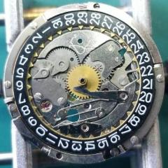
I’m currently working on a vintage Cortébert 677S movement. During strip down I came across a wheel pivot tightly friction fitted through the train bridge to another on the underside. It reminded me of some Smiths double wheel assemblies but obviously these are supposed to be separated to clean the jewel holes and lubricate. I’m sure given the right amount of pressure they’ll separate. I’m guessing the friction fitting is similar to a centre wheel through a canon pinion. Does anyone have any advice on tackling this safely without risking damage to any of the components? Photos of issue shown.

Thanks!

f9eec5e98ca5e73a3f2c4d58a50e7fea.jpg

16d64942dc398d56727bdfa78207bb35.jpg

40586eaf7c8191c366ab1ce810a08f4e.jpg

83c81e5e946c0b5397295f5e83934e91.jpg

8681d34e5900f5add835d9497510e1aa.jpg


Sent from my iPad using Tapatalk

Link to comment
Share on other sites

When I read your subject title I thought this was going to be something to do with social distancing!!!  :D


The wheel on the top of the plate (which drives the center seconds pinion) is a friction fit onto an extended pinion that comes through the plate, a bit like a sub second pinion goes through the main plate.

There is a specific Presto style remover (mine is Bergeon 30638/3) for removing this wheel but it can be done with levers or even razor blades. The key thing is to ensure that the wheel is lifted vertically so that there is absolutely no bending force on the pinion as it is very brittle and easy to break, otherwise it should be relatively easy to remove.

Reassembly is also easy, especially if you have a staking set.

  • Like 3
Link to comment
Share on other sites

 I agree with Marc use a presto tool specific for this job. Looking at your pics measure before and lift the wheel from the underside (would be best if poss) so as not to distort the other wheel. The key to this job is a very straight lift. Also when re-stalling a straight push putting the wheels to the same positions on the arbour . 

  • Like 1
Link to comment
Share on other sites

Thanks for all your quick responses.

Nucejoe, I’m just concerned that by not separating, I’m unable to easily lubricate the jewel holes after cleaning. However, I don’t have a presto tool (I have an old Star No.230 tool I use instead). Maybe an excuse to buy the required tool though!

Thanks!


Sent from my iPhone using Tapatalk

  • Thanks 1
Link to comment
Share on other sites

9 minutes ago, Nucejoe said:

With all due respect to both gentleman above.I just clean in place, these independently driven minute wheels and save yourself a headache. Regards

Tempting, I  must admit Joe especially if you do not have the correct tools. However checking to see if the pivot is scored will not be possible so I would remove. 

  • Thanks 1
Link to comment
Share on other sites

On 4/1/2020 at 9:49 AM, AdamC said:

Maybe an excuse to buy the required tool though!

If you decide to buy the presto type tool then be aware there are 2 variants - one for 5 spokes and one for 6

https://www.cousinsuk.com/category/train-wheel-removing-tools

They are quite expensive if you buy new. I got mine second hand, but before I had them I did this successfully with a pair of knife blades inserted under the hub of the wheel.

  • Like 1
Link to comment
Share on other sites

Thanks for sharing your thoughts Stuart. I went ahead and bought the 5 spokes version from Cousins based on Marc’s suggestion earlier in this thread. What I’m saving on not going out at weekends has paid for that! Hopefully it will arrive today/tomorrow and I’ll look forward to giving it a go. Will also be a useful tool to add to my slowly growing arsenal.

Cheers!


Sent from my iPad using Tapatalk

  • Like 1
Link to comment
Share on other sites

  • 2 weeks later...

Just to complete this post, I'm pleased to say that the Bergeon Presto 30638-3 tool I bought worked a treat (photos to illustrate). The movement has now been cleaned, lubricated, and is in working order. I particularly found the BHI paper on the 'Practical lubrication of clocks and watches' interesting and have decided to swap my Moebius D5 oil for Moebius HP 1300 synthetic.

Thanks to everybody that contributed. oil.20200403_225709952_iOS.thumb.jpg.0923e91745364eab9b84dac15951fbd2.jpg


20200403_230323687_iOS.jpg

Edited by AdamC
  • Like 1
Link to comment
Share on other sites


  • Recently Browsing

    • No registered users viewing this page.
  • Topics

  • Posts

    • Unfortunately I'm not that lucky. I started on the train side and after I noticed the binding I pulled everything out except the driving wheel to rule everything else out. It still binds. I'm going to double check that the pinion is fully seated on the staff first, then if no joy I'll push the bridge jewel up a fraction of a mm. Fingers crossed!
    • Happy to have helped, great way to start the day with a win! 🥳
    • Thank you for the advise!! It worked. The setting screw was a lock/unlock to remove the rotor. 
    • I have that French tech sheet too, it is a little different than the English one (eg, it doesn't have the auto works diagram). BTW, it looks like you are looking up the case number in the 1979 ABC supplement. The 1974 ABC catalog does have the 3093 case. As you determined it takes the 1222-5 crystal.  When I serviced my President 'A' (which also takes that crystal), I was able to fit a 29.8 crystal from my DPA crystal assortment. Those are, in my opinion, a great deal. The assortment comes with 10 sizes each from 27.8mm to 32.4mm in 0.2 increments. I pretty much use them for any non-armored crystal that takes a high dome crystal. I think they no longer make them but Cousins has still has some in stock but when I bought them they were around $40 for the set and now they are around $100. Still, at 40 cents a crystal it's still a good deal. For the large driving wheel, I remember I once assembled the keyless/motion works first and when I placed the large driving wheel it was interfering with the setting wheel on the dial side as the teeth were not fully meshing and it wouldn't fully seat. If that isn't the issue I got nothing and am looking forward to see how you solve it 🙂
    • Not sure, but just looking at it, it seems like the screw on the right may be a fake? The one on the left may not be a screw in the regular sense at all, rather a 2 position device, I think you need to point the slot towards either of the 2 dots and one will secure and one will open. Like I said this is just my best guess looking at the pictures.
×
×
  • Create New...