Jump to content

favre leuba spring


gary17

Recommended Posts

Hey

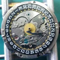
This is a favre leuba cal 253 .Can any one tell me were this spring goes to return the clutch lever. If i put it were i think it goes (see first pic).

The wheel don't fit right. it to high , the setting bridge wont locate. But i cannot see were else to put it.

any suggestions.

Or diagrams.

cheers

gary

IMG_20191213_225746.jpg

IMG_20191213_225627.jpg

Link to comment
Share on other sites

Did you notice your setting lever has a protruding pin? Normally the spring would go behind the lever doesn't look like there's room?  So looks like your spring should have the long part pushing on the protruding pin of the lever the rest of it will go in the  recessed area next to it then the plates will go on top and hold everything in place.


http://www.ranfft.de/cgi-bin/bidfun-db.cgi?10&ranfft&0&2uswk&Favre-Leuba_253


Link to comment
Share on other sites

Hi

Yer the problem seems to be were the spring is secured. When you put the wheel on top of the spring there is nothing left of the column to locate the bridge. If you try the spring will not stay in position. I was hoping someone had come across this problem. 

Regards

Gary

Link to comment
Share on other sites

Does the spring not fit as shown, behind the lever, rather than locate on the pin (column) on top of the lever.

SpringIssue.jpg.76be9fcab76ceb6f7f71db0d874ece99.jpg

The pin (column) is there to locate the upper keyless lever, not to locate the spring I think.

When fitting, take care not to launch it in to space (cover with tip of pegwood, or a blob of rodico when fitting). Place the upper lever immediately after fitting to avoid any flying spring incidents.

Edited by AndyHull
Link to comment
Share on other sites

I would disagree with the location of the spring in the picture above the reason for this is in the picture I have the post circled in green has a wheel that goes there missing in this picture would be helpful if that would go back on its post. Then there's zero space behind the setting lever to put in a spring at all. This is where the protruding post becomes interesting and the circular recess that's level with the spring. So in my version the drawing you can see what I think the spring should go.

jumper spring.JPG

  • Like 2
Link to comment
Share on other sites

3 hours ago, JohnR725 said:

I would disagree with the location of the spring in the picture above the reason for this is in the picture I have the post circled in green has a wheel that goes there missing in this picture would be helpful if that would go back on its post. Then there's zero space behind the setting lever to put in a spring at all. This is where the protruding post becomes interesting and the circular recess that's level with the spring. So in my version the drawing you can see what I think the spring should go.

jumper spring.JPG

I agree, the green circled area is where another gear is supposed to go (otherwise you won't be able to set the hands).

The spring most likely goes where the pink mark is. Sometimes these springs don't have an obvious-looking designated spot where they go, I guess that's how some makers made their movements back in the days.

Link to comment
Share on other sites

A quick look at the parts catalogue sheet on Cousins suggests that your spring isn’t quite the right shape which will always make the guesswork harder. Cousins has them in stock at only £2.20 so worth getting a replacement.

The installation is a little unusual, but the Google drive link in this thread has a pretty good image

https://www.watchrepairtalk.com/topic/1919-favre-leuba-253-service/page/2/

There is also a suggestion in that thread that the barrel arbours might not both be the same. Worth a check they are in the right places.

Link to comment
Share on other sites


  • Recently Browsing

    • No registered users viewing this page.
  • Topics

  • Posts

    • Unfortunately I'm not that lucky. I started on the train side and after I noticed the binding I pulled everything out except the driving wheel to rule everything else out. It still binds. I'm going to double check that the pinion is fully seated on the staff first, then if no joy I'll push the bridge jewel up a fraction of a mm. Fingers crossed!
    • Happy to have helped, great way to start the day with a win! 🥳
    • Thank you for the advise!! It worked. The setting screw was a lock/unlock to remove the rotor. 
    • I have that French tech sheet too, it is a little different than the English one (eg, it doesn't have the auto works diagram). BTW, it looks like you are looking up the case number in the 1979 ABC supplement. The 1974 ABC catalog does have the 3093 case. As you determined it takes the 1222-5 crystal.  When I serviced my President 'A' (which also takes that crystal), I was able to fit a 29.8 crystal from my DPA crystal assortment. Those are, in my opinion, a great deal. The assortment comes with 10 sizes each from 27.8mm to 32.4mm in 0.2 increments. I pretty much use them for any non-armored crystal that takes a high dome crystal. I think they no longer make them but Cousins has still has some in stock but when I bought them they were around $40 for the set and now they are around $100. Still, at 40 cents a crystal it's still a good deal. For the large driving wheel, I remember I once assembled the keyless/motion works first and when I placed the large driving wheel it was interfering with the setting wheel on the dial side as the teeth were not fully meshing and it wouldn't fully seat. If that isn't the issue I got nothing and am looking forward to see how you solve it 🙂
    • Not sure, but just looking at it, it seems like the screw on the right may be a fake? The one on the left may not be a screw in the regular sense at all, rather a 2 position device, I think you need to point the slot towards either of the 2 dots and one will secure and one will open. Like I said this is just my best guess looking at the pictures.
×
×
  • Create New...