Jump to content

Digital Hairspring Timing Tool


margolisd

Recommended Posts

15 minutes ago, jdm said:

Be well seated before opening the price list.

That phrase sets the cliche "parsimonious Scotsman" in me in "to how could I do that better (i.e. cheaper) mode".... 

I presume that it works by twitching that control arm, and "listening" to the resulting resonance, then repeatedly tweaking the frequency of the "twitch" until maximum amplitude is obtained. 

Does anybody know if my presumptions are correct?
 

Link to comment
Share on other sites

Oh wow. If I had 3500 Euros... 

I've recently been trying to make a virtual hairspring vibrating tool using my iPhone. It has some potential. The phone glass is a perfect surface to vibrate the wheel on and you can sync it to an animation. It's triggering the balance at the correct time with the correct force that is tricky.


Link to comment
Share on other sites

4 minutes ago, HSL said:

Looks like a project one can have in the que..

There are probably hundreds of hours spent on design, prototyping, refinement and production setup. Considering that the price of €3,500 is not out of this world.

Link to comment
Share on other sites

This is what I use for hairspring work (and some of the best German watch manufacturers, too).
Price however is just a fraction of the above mentioned, I am sorry... [emoji6]
Frank

 
spirdose_flde_c.pdf
That's awesome, is it your invention?

I have a Spiromatic, which is a very cool machine, but it's a curiosity on my shelf- the Luthy tool gets used as it's just simpler for onesies (sometimes with a stopwatch when I do a weird Lecoultre with 20222 or 20944 for example). I'd be interested in the one you posted.
2e6ec7396d0b1b5eec21d07d9085df40.jpg8789ec22d353d1df75f6e17a087615f2.jpg
Link to comment
Share on other sites

Hello,

I love this Greiner Spiromatik. Years ago I owned one and planned to update the old electronics and replace the huge display box, but gave it to a collector before. Still have another type of the 50s, it works with a pallet-like part that drives the balance under test.

Drawback of these machines is, they are for serial work and must be equipped for the target calibre.

Yes, above was my development. You will get a PM.

Frank

Link to comment
Share on other sites

  • 2 weeks later...
On ‎8‎/‎19‎/‎2019 at 6:35 PM, AndyHull said:

That phrase sets the cliche "parsimonious Scotsman" in me in "to how could I do that better (i.e. cheaper) mode".... 

I presume that it works by twitching that control arm, and "listening" to the resulting resonance, then repeatedly tweaking the frequency of the "twitch" until maximum amplitude is obtained. 

Does anybody know if my presumptions are correct?
 

I think there would be several possibilities to make a device like that to work. This sunday I got an hour to myself from my other household duties so I sat down and thought things throug. Eldery devices use a finely tuned spring and balance to compare the oscillation against, when the two balances are in sync you make a reading towards a scale.
But modern equipment probably need something else to detect the spokes on a balance, since it's rotating on its pivot I don't think you could use sound to determine the oscillation. One probly wouldn't want to touch anything on the setup so two methodes comes into mind:

1. Use a Hall sensor.
2. Use light sensitive electronics.

I think a hallsensor would work really good but I don't know how small thiny hairsprings would react to an electric field so I will go for a light sensitive sensor.
Just out of chance I pulled out a TCRT5000 Reflective Infrared Sensor out of my Arduino toybox and made a preliminary test.
I sometimes design high speed odometers for autonomous vehicles so this was a different challenge, to get a device which detect low frequencie movements. A hairspring in some cases oscillate at 18000 A/h which is a frequency off (18000/3600) 5Hz.
The setup was able to detect even lower frequencies so I don't Think the Electronics will be the challenge but the design of the sensor setup might take an hour or two. I plan to use a non polarizing glas from a microscope on which the balance can spin freely.
I only took 20 minutes this time to prove the concept and it will probaly work like a charm so this is something I will put into the projects que for fun things to do with your 3-D printer a dark Nordic Winter night.


IMG_20190902_083128.jpg

  • Like 1
Link to comment
Share on other sites

I have some bare opto-isolators that look similar to the one on that board in your picture. I was using them to hack a serial interface in to cheap multimeters a couple of years back and since it was cheaper to pick up ten from china than one from a local supplier, I have quite a number lying unused.

I guess the trick would be to either get the balance to spin between the LED and the photo transistor or bounce the light from below and catch the reflections on the photo transistor.

Using a glass microscope slide sounds like a good option to spin the balance on, with perhaps a blacked out lower surface with a slit in it to shine the LED transmitter light up through. You might need to modulate the light somehow to help distinguish it from any background infra red.

As you say, a project for the rapidly approaching dark winters evenings I suspect.  

Link to comment
Share on other sites

  • 6 months later...
On 9/2/2019 at 3:12 AM, HSL said:

I think there would be several possibilities to make a device like that to work. This sunday I got an hour to myself from my other household duties so I sat down and thought things throug. Eldery devices use a finely tuned spring and balance to compare the oscillation against, when the two balances are in sync you make a reading towards a scale.
But modern equipment probably need something else to detect the spokes on a balance, since it's rotating on its pivot I don't think you could use sound to determine the oscillation. One probly wouldn't want to touch anything on the setup so two methodes comes into mind:

1. Use a Hall sensor.
2. Use light sensitive electronics.

I think a hallsensor would work really good but I don't know how small thiny hairsprings would react to an electric field so I will go for a light sensitive sensor.
Just out of chance I pulled out a TCRT5000 Reflective Infrared Sensor out of my Arduino toybox and made a preliminary test.
I sometimes design high speed odometers for autonomous vehicles so this was a different challenge, to get a device which detect low frequencie movements. A hairspring in some cases oscillate at 18000 A/h which is a frequency off (18000/3600) 5Hz.
The setup was able to detect even lower frequencies so I don't Think the Electronics will be the challenge but the design of the sensor setup might take an hour or two. I plan to use a non polarizing glas from a microscope on which the balance can spin freely.
I only took 20 minutes this time to prove the concept and it will probaly work like a charm so this is something I will put into the projects que for fun things to do with your 3-D printer a dark Nordic Winter night.


IMG_20190902_083128.jpg

Do you still have the arduino code for this system you created?

Thanks

Link to comment
Share on other sites

Join the conversation

You can post now and register later. If you have an account, sign in now to post with your account.
Note: Your post will require moderator approval before it will be visible.

Guest
Reply to this topic...

×   Pasted as rich text.   Restore formatting

  Only 75 emoji are allowed.

×   Your link has been automatically embedded.   Display as a link instead

×   Your previous content has been restored.   Clear editor

×   You cannot paste images directly. Upload or insert images from URL.


  • Recently Browsing

    • No registered users viewing this page.
  • Topics

  • Posts

    • Thank you to both of you!  I've been somewhat derailed by this quandary for a couple of days now. I am guessing that the point of the wider tweezers is to support the whole spring at the same time in an effort to prevent it going under tension... I have already discovered the Zen of a clutter free space, and trying to keep my work well away from the edge, however the most terrifying of the flights wasn't so short, I had my work in the middle of the table and nothing else around.  That particular launch was towards me.  I distinctly recall feeling the spring hit my left hand as it escaped.  I only found it by dumb luck, on the floor, between the legs of my chair.  I need to order a pack of replacements just in case.  I think I recall a thread discussing where to find them, and the differences between the clones and the authentic ETA ones, pointing out that they're not interchangeable (the clones being longer IIRC).  Now I just have to find that thread again.  What I haven't mastered is the zen of the search function here.  I'm sure I"ll get that down eventually. So this is similar to, but different from one of the posts I had found in my original searches (or maybe I'm just hallucinating, I can't find the post I thought I remember).  The bits about the corner filled in a gap in what I'd read before.  At least I have a more clear picture in my head about what needs to happen now.  Yes, I've learned about how touchy these springs are.  What I'm not sure I have a good grasp on is the understanding of what causes the spring to flex, other than to say "the slightest little touch"  I think I'm going to try a small bit of Rodico to position the spring next time.
    • I think it's stamped on the inside cover. 309 I think.
    • Hi all, needing a little help. I have an old Casio AQ-321G, but have no idea what battery it takes. I've looked around online, but cannot see anything... I see a 309 stamped on the case back, could this be it....? Can you please help, below are some pictures:
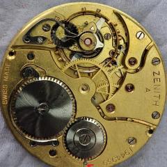
    • The radial teeth are for hte seconds register, and the other (which is simple and doesn' take away significant torque from the train) for the minutes register.
    • The original 6139A manual is very clear in how to disassemble and how to assemble ...... step-by-step. However I haven't seen the 3169B manual, even in the Japanese version around, which clearly highlights the difference in center-wheel.   6139A Seiko Technical Guide.pdf 6139_A.pdf 6139A.pdf 6139b.pdf 6139B repair guide jp.pdf        
×
×
  • Create New...