Jump to content

Landeron 248 modified 4th wheel


Recommended Posts

Hi Gents,
 

Currently, I try to recondition a 1970 Regency chronograph with a Landeron 248 movement. 


Everything is going fine so far. Ordered new mainspring, glass, gasket and pushers as they were a bit stiff. The case itself has been replated as it was also quite worn. I dismantled the whole movement and this is where I have some problem and I would like to ask more experienced members' opinion as I am only a novice.

Straight to the issue, I could not remove the 4th wheel. For me, it seems that the bottom of the 4th wheel pivot was formerly broken but still long enough to sit in the 4th wheel bottom jewel hole. In addition, it looks that a small pipe or so was fitted from the bottom plate to the end of the 4th wheel pinion. And this is the reason that I cannot remove it. 

Could it have happened as I detailed above or it is a normal thing? Should I remove it anyway and change the whole 4th wheel or the pinion if I can manage to find a replacement. What can be done? what do you suggest?

After this, I decided to carry on like that and at the end when I will measure the accuracy, it should show some really bad results in case if there is any affection.

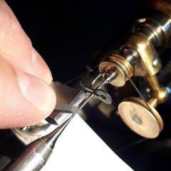
And now got to the second issue. So, at the end of the cleaning, I found a small pin in the bottom of the horosolv jar. I managed to find its place. However, I am not quite sure how to fit it again. To be honest, I cannot see its purpose really. From the bottom end, it is underneath the setting lever, and from the top plate also it sticks out hardly any. 

Have you got any idea how to solve these problems?
 

Sorry for the poor quality of the pictures. Hope they help though.
Please detail your answers as I am just a beginner.

Any help is much appreciated.

Gabe


P.S.: Please ignore the notes on some of the images which are not related to my issues. Thanks.

40520856_s-l1600(4).thumb.jpg.92f4a5eb18b54d7d9ca701ecf2dd2698.jpg

1892249721_WhatsAppImage2019-07-18at11_24_40.thumb.jpeg.00d799657ad45a91f66e4c99dd853e50.jpeg1204557455_WhatsAppImage2019-07-18at11_24_36.thumb.jpeg.10cffbbf3474363fccedf7cf4baa0058.jpeg

1782921740_InkedWhatsAppImage2019-07-18at11_23.39(2)_LI.jpg.055118501eeed87104b98feb853c1509.jpg8160902_InkedWhatsAppImage2019-07-18at11_23.15_LI.jpg.73c6d306acd2c28161a45dfdb68ced8d.jpg2140671115_WhatsAppImage2019-07-18at11_23_37.thumb.jpeg.5a0efade479384269438189ca2fac9d0.jpeg19035398_WhatsAppImage2019-07-18at11_23_15.jpeg.777ee2cdccdd2a1fd5abe12fb76e56ec.jpeg

306281800_WhatsAppImage2019-07-18at11_23.38(1).thumb.jpeg.2e6024fee41e0c7e9b1b3c6e0b20761d.jpeg1593514737_InkedInkedWhatsAppImage2019-07-18at11_23.39(3)_LI.thumb.jpg.b7f6f2115c3dfd3d7b29b3d6b4ebbcef.jpg


Link to comment
Share on other sites

That little modification isn't a very good modification, it will require you to modify any pivot on the replacement wheels you buy since I guess the inner diameter of that tube isn't the same as the diameter of the original jewel hole. I  would have replaced the jewel and put a new 4th wheel in.
If the screw you arre woundering about is the one in the 3:rd picture then it is just a normal screw from the bridge, it should come ontop of where it is now when you put the trainbridge back.


  • Like 1
Link to comment
Share on other sites

Yes the loose pin is a guide pin from a bridge, but from which you have to find out your self.
I'm still pussled about that tube in the jewel, how is it supposed the lubrication comes on to the wheel pivot from the oil cup? 
 

Landeron 248.jpg

Edited by HSL
Swedlish
  • Like 1
Link to comment
Share on other sites

  • 2 weeks later...

Guys,

Apologies for the late reply, I was quite busy in the last couple of weeks and not much has been done since. I designed a mainspring winder as they are quite pricy. But I stuck in a bit as I've been waiting for weeks now to get 3d printed by a friend. Until today, as finally, I persuaded my wife about 3d printers so I ordered my first entry-level machine. (Cetus mk3)

Also, I'm not sure how to deal with the worn dials. Recently, I've seen Mark's video how he printed his own dial designs. So I am going to try that way and keep the original dial in case I decide to sell the watch. First of all, I had to make a plain replacement dial with the holes and legs. The surface still needs to be polished before anything is attached.

I also checked the small minute hand. This can also prove how amateur I am in watchmaking. Delgetti, exactly as you said. Part of the minute hand stuck on the pivot of the 4th wheel so hard that I am still surprised by how I could manage to remove it without breaking the pivot.

In regard to the pin, I found its exact location, in the keyless work right underneath the setting lever. The setting lever is quite loose now even if it was not removed or loosened over the cleaning. I remember it was not wobbling at all. So, I assume that the pin adjusts the hight of the setting lever and also makes less friction as the lever comes into contact only with the top of the pin while it slides. 

Any ideas how to fit it back? I can set how much it has to stick out because there are marks on the pin. But should I solder? I'm afraid of damaging other features on the plate.

I have another silly question about oiling the movement. Would it be acceptable to use 8300 natural grease where 9501 synthetic grease is advised (keyless work etc.)? In the future, I will need to buy some but now I spent way too much on this project.

Sorry for the novel.

Guys, your experience, knowledge and help are highly respected and much appreciated.
Thank you,

pin_03.jpg.df8a66ab22febedb5ccca9497ab1644d.jpgpin_01.jpeg.a8d9a5bcbb79addce42bc9392de1009e.jpegpin_02.jpeg.8e383ce1eaaba5f1eb105ece7242bb08.jpegmswinder_01.thumb.jpeg.a5ec6c4027e89fa4d30d9d1f026569b3.jpegmswinder_02.thumb.jpeg.bb2fe07e644850e393d18302eab38d9c.jpegdial_01.thumb.jpeg.2219a79a48cb1d58c837266ec45d0bc1.jpegdial_02.thumb.jpeg.bc3e4fcf77aa85ff77fe8c732c092418.jpeg

Link to comment
Share on other sites


  • Recently Browsing

    • No registered users viewing this page.
  • Topics

  • Posts

    • Welcome to the group Stirky. You can search for just about every subject in the craft here. Don't be afraid to ask if you can't find the answer that may have already been covered ( some ad nauseum LOL ). You don't have to buy Bergeon to get good quality. There are many decent mid-range tools available that will last you a lifetime. Cousins would be a good place to start . Cheers from across the pond ! Randy
    • I picked up a similar amount of these jewels some years ago in a watch and clock fair. Every now and then they come in handy. This week I've got a rubbed in bombe jewel in the balance cock that is cracked and needs replacing. Very handy to have a vintage assortment of these type of jewels!
    • Great diagram with the teeth and pinion count. Simple way to reduce the speed of the hour wheel by the 12:1 minute wheel. Genius and yet so simple. Always good to reinforce the principal by what you have done in your drawing. Keep doing that. I had a drawing on my wall for years showing me this which is very similar to the drawing you have done. Here's a formula to work out the beats per hour of a watch movement. The movement's BPH is dictated by the wheel teeth and pinion count and the hairspring being vibrated to the correct BPH by finding the pinning up point on the hairspring using a vibrating tool.  The reason in the formula there is X2 on the top line is because there are two pallet stones.
    • So I just wanted to say "thank you" again.  The angle is the key bit it seems and yes, it did basically just fall, or float, back into position when I got it lined up just right. I had meant to add that now that I see how it goes in, I totally see how it came out in the first place, and that whomever cloned the original movement didn't pay much attention to the fine details around the setting or how it interfaces with the balance cock or the "rings" on the regulator and/or stud carrier arms.
×
×
  • Create New...