Jump to content

Custom Build using Venus 170


Recommended Posts

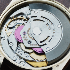
Well fiddle sticks!!!! I have corrected one problem but created another. I figured out that I didnt have the hammer mounted correctly. I fixed that and things seemed to function a bit better at least between depressing the buttons. I got a little confident and figured the crazy reading I was getting on the time graph was due to a bunk balance. So I decided to look into it. I have two assemblies. After a closer look these too seem to be different. I noticed the hair springs didnt seem to have a nice concentric layout when put in place so I decided to try and tweak them. That was a mistake. So far the only thing that really makes me a bit nervous is when I start messing with the hairspring. If I can find a good balance assembly id rather just drop the coin on it rather than try to fix them. Ive included pics of them. I will order a complete balance assembly, if I can find one. I have a hunch that the grinding im feeling when turning the stem is due to a bad sliding gear so I am going to swap that out as well. d4cd380d80e22ff2d45eb1777935b045.jpg3510d3e40270754cd41ced59ebdc5903.jpg

Sent from my SM-G950U using Tapatalk

Link to comment
Share on other sites

Apologies for not posting in a while.  the 3D printer should be here this weekend.  I also ordered a copper electroplating kit and plan to use it to do some plating.  I have also ordered two new complete balance assemblies. I met a fellow at www.scotchwatch.com where I purchased the balance assemblies.  A real nice guy, Blake Scott.  He provided me with some pretty helpful information regarding the variation in movements.  I thought it would be helpful to include some of his comments here.  I noticed that one of the balance assemblies I had included an incabloc type of jewel.  I had always though that the 170 did not have this type of set up....well, I was wrong.

"I believe the inca version was something for breitling only and it would have been available through them only. Venus and the other swiss mfgs did special things for brands that they never released into general production. I say that because I do not have any of the inca bridges(main or balance) in my stock. I asked just to be sure I did not ship you the wrong thing."

"The variances in part design you see are normally improvements made over time and unless noted most times the parts are interchangeable with the older versions, but not always true. This is normal with regard to all swiss movements. Valjoux 23/72 calibers are a very good example of this. Brands made changes and the mfg made changes as production rolled along and it can get confusing."

Anyhow, I hope Blake doesn't mind that I quoted him.  He also offered to assist if I had any questions.  Its people like this that make this venture worthwhile.  I have a 7750 that I am working on so it may be a couple weeks before I get back to the 170 project.  A quick note to add, and I may be wrong but so far all of the evidence that I have found says that there are no more balance assemblies being produced so that means the stock is finite.  If you are going to pick up this movement for repair you may want to scrounge up all the balance assemblies you can......

Stand by.


Link to comment
Share on other sites

Still rolling. 3D printer has been set up, calibration completed and test part completed. The pushers have also arived as well as the two complete balance assemblies. I also tested out the electroplating set up. Some minor issues with that and I have a couple inquiries to the manufacturer. I plan to gold plate all the steel workings and anodize aluminum parts including main plates and bridges. The color chosen for anodize is red. I have been procrastinating on one important milestone....and that is a successful assembly of the movement. My plan is to attempt an assembly this upcoming weekend. Wish me luck. 41204289b6040d88fb0c0a1a371d3163.jpg2115c66e47e7c1ef96de918fbe1bf75b.jpgb0d59eb949e58efd5d7cbf30b6ab6917.jpg

Sent from my SM-G950U using Tapatalk

Link to comment
Share on other sites

Nice. I'm particularly keen to see how the plating goes.

I've seen various methods for plating steel, but my understanding is that you will need to plate with copper first (either by dipping in copper sulphate solution if the steel reacts correctly with that, or electroplating with perhaps home made copper acetate). 

Who is the plating supplier, and what method do they recommend?

Edited by AndyHull
Link to comment
Share on other sites

Nice. I'm particularly keen to see how the plating goes.
I've seen various methods for plating steel, but my understanding is that you will need to plate with copper first (either by dipping in copper sulphate solution if the steel reacts correctly with that, or electroplating with perhaps home made copper acetate). 
Who is the plating supplier, and what method do they recommend?
I dont think im at a level where I can recommend anything lol. But I will def share my findings. Im using kits from caswell. They have pretty solid instructions. Youre right though....stainless needs to be treated with a product called zincate prior to plating. The functioning parts on the 170 I think are just steel so they will take an activator prior to gold plating, although im not 100% certain on the material type. They are fairly magnetic so im guessing they arent stainless. I also have their black nickel kit and flash copper kit. I have a lot of spares of the 170 so Im going to do some experimenting. They also have a surface activator solution for aluminum parts which im going to test out. Otherwise ill send the aluminum parts out for anodizing as the anodizimg kits are pretty expensive and the process is fairly complex for the general hobbiest. Ill def post some findings. Thanks for checking out my thread.....I was getting a bit lonely here. Lol.

Sent from my SM-G950U using Tapatalk

Link to comment
Share on other sites

Nice. I'm particularly keen to see how the plating goes.
I've seen various methods for plating steel, but my understanding is that you will need to plate with copper first (either by dipping in copper sulphate solution if the steel reacts correctly with that, or electroplating with perhaps home made copper acetate). 
Who is the plating supplier, and what method do they recommend?
One more thing.....ive also been a bit concerned about what the plating will do in terms of fitment.......we shall see.

Sent from my SM-G950U using Tapatalk

Link to comment
Share on other sites

I did a few simple experiments with copper and copper nickel coins a couple of months back, using vinegar with a pinch of salt as the electrolyte. You can also use backing soda.

The copper plated really well using a 5v USB charger. Interestingly using a couple of 20 pence (UK) coins, which are copper nickel, I wound up plating the copper out of the coin, and had a black powder fall to the bottom of the jar. I suspect this is nickel, or nickel oxide but I didn't try melting or a flame test to verify this.

I've got a nickel electrode on its way on the slow boat from China, so I'll try a few experiments with that too.

One important thing, make sure the surface you want to plate to us surgically clean and de-greased. Any fingerprints or dust will ruin the finish. Also plate slowly, 5V gives a  better result  than 12V, but takes longer. I cleaned with detergent and dipped the piece in acetone prior to plating.  

I also intend to mess about with a small variable current variable voltage power supply that I have, to see if it makes any difference. 

Also be aware that you do end up with some "interesting" solutions of metal ions which need to be disposed of carefully, particularly if the work piece has chrome or other toxic metal on it.

Even copper and nickel solutions are environmentally hazardous. If you don't fancy having jars of toxic liquids lying about I suggest you gently evaporate off the water and keep the resulting metal salt crystals in labelled child proof medicine bottles for later use.  


Link to comment
Share on other sites

I did a few simple experiments with copper and copper nickel coins a couple of months back, using vinegar with a pinch of salt as the electrolyte. You can also use backing soda.

The copper plated really well using a 5v USB charger. Interestingly using a couple of 20 pence (UK) coins, which are copper nickel, I wound up plating the copper out of the coin, and had a black powder fall to the bottom of the jar. I suspect this is nickel, or nickel oxide but I didn't try melting or a flame test to verify this.
I've got a nickel electrode on its way on the slow boat from China, so I'll try a few experiments with that too.
One important thing, make sure the surface you want to plate to us surgically clean and de-greased. Any fingerprints or dust will ruin the finish. Also plate slowly, 5V gives a  better result  than 12V, but takes longer. I cleaned with detergent and dipped the piece in acetone prior to plating.  
I also intend to mess about with a small variable current variable voltage power supply that I have, to see if it makes any difference. 
Also be aware that you do end up with some "interesting" solutions of metal ions which need to be disposed of carefully, particularly if the work piece has chrome or other toxic metal on it.
Even copper and nickel solutions are environmentally hazardous. If you don't fancy having jars of toxic liquids lying about I suggest you gently evaporate off the water and keep the resulting metal salt crystals in labelled child proof medicine bottles for later use.  
 
Heck yeah....see I need to be asking you for recommendations. Check out the caswell products page and tell me what you think. I have a few inquiries into them based off my last attempts. I have been cleaning my parts with dish soap, but will def use the acetone prep as well moving forward. Ill let you know how things go. This project has a ton of mini projects about it. The first 3D print came off nicely. I also have to crack the movement assembly. Any idea what the plating adds. I read the flash plating only adds about
.0002"-.0005". Which isnt much but could affect assembly. As for the anodize thats more or less a dye, but with that im wondering if ill need to remove the plate jewels. A lot of ifs in this build. Lol.

Sent from my SM-G950U using Tapatalk

Link to comment
Share on other sites

Andy - I bought a brush olating kit from these guys, which takes a lot of the guesswork out. https://www.classic-plating.co.uk/. Starting point was rose gold plating some watch hands and it worked perfectly first time out.

bjd - those plates and bridges are going to be brass not aluminium. They are likely already plated with rhodium or similar which is why they aren’t brass coloured.

Link to comment
Share on other sites

I'm no expert when it comes to plating, but reading up on the subject and watching a few videos has given me some good tips.

Here are a few thoughts from what I have gleaned so far.

The thickness of the plating is a function of time and current, however if you boost the current, you tend to get dendrites forming (whiskers of metal), which is not what you want, so increasing the time and keeping the current low seems to be the way to go. (There is a little more to this, but that covers the basic idea). In theory you can make the plating as thick as you want, but in reality, there are obviously some limiting factors if you want to preserve the physical dimensions, and details of your piece.

Commercial gold plating is usually expressed in microns and from what I have gathered so far, generally watch case plating is in the 10 to 50 micron range. Obviously the thicker the Gold plating the better, as it will be more durable,  but also the more it will cost.

Some of the plating refreshing kits put very little gold down (maybe 1 or 2 microns), so although they look good, and will be fine for touching up damaged plating, they are not going to last as long as a full re-plating.

You can plate pretty much anything if you can make it conductive, and compatible with your plating solution, as this video demonstrates.

Now I don't know how long the plating would last on a copper plated minion, but I suspect since the body is plastic, it would have a tendency to de-laminate.

Once you have copper, or some other suitable metal on your work piece, you  can add gold, silver, rhodium or whatever, but this is where the chemistry becomes a bit more interesting.

My understanding of large commercial scale gold plating is that it has traditionally used cyanides to dissolve the gold, (cyanides are also used in some gold mining operations),  which makes it somewhat dangerous. Most of the plating solutions you get on the internet will uses slightly safer chemistry, but may (arguably) be less effective. 

For best results, work slowly, keep everything as clean as possible, and keep us posted with your results. 


Link to comment
Share on other sites

4 hours ago, StuartBaker104 said:

Andy - I bought a brush olating kit from these guys, which takes a lot of the guesswork out. https://www.classic-plating.co.uk/. Starting point was rose gold plating some watch hands and it worked perfectly first time out.

That certainly looks like a more sensible move than trying to do it from scratch. I have, or can improvise most of the stuff you need, the power supply and so forth, so I may just purchase their gold plating solution. Thanks for the link.

Link to comment
Share on other sites


bjd - those plates and bridges are going to be brass not aluminium. They are likely already plated with rhodium or similar which is why they aren’t brass coloured.


Thanks Stu, duh. I should have known that. It will help however when deciding the plating options. It does remove the anodizing option.

Sent from my SM-G950U using Tapatalk

Link to comment
Share on other sites

5 hours ago, AndyHull said:

That certainly looks like a more sensible move than trying to do it from scratch. I have, or can improvise most of the stuff you need, the power supply and so forth, so I may just purchase their gold plating solution. Thanks for the link.

Yes I think you do, I was eager to learn about plating some years ago so I bought one of those kits and got a surprise when it got home, the "lab power source" was an ordinary adjustable power supply nothing I would use in the lab. But their solutions for plating is probably one of the best.
Fortunately they have a guide too online and it goes through everything you need to know.
https://www.tifoo.de/media/pdf/bf/6d/3e/handbook_for_plating_1_2.pdf

Link to comment
Share on other sites

1 hour ago, bjd1020 said:

Copper plating turned out well on the main plate. Thanks for the acetone tip. b4462c2652935c0c4c167d87cdc222b9.jpge181b8bfde106044805fdc35e22f1386.jpg

Sent from my SM-G950U using Tapatalk
 

That looks pretty good. Take a look at the guide HSL linked above, it gives a bunch of very useful tips. Did you remove the jewels prior to plating, or leave them in situ to avoid the holes from closing due to the plating solution?
I suspect that leaving them in, but blanking them off with a wax plug to avoid any unwanted reactions or contamination might be a good option.

Edited by AndyHull
  • Like 1
Link to comment
Share on other sites

That looks pretty good. Take a look at the guide HSL linked above, it gives a bunch of very useful tips.
Thanks. Ive read thrpugh about half of so far and yes it has a ton of useful tips. Thanks for posting.

Sent from my SM-G950U using Tapatalk

Link to comment
Share on other sites

13 hours ago, bjd1020 said:

Run 2 complete

I couldn't help noticing your 3D printed prototypes seemed to be lacking holes for pushers and the stem.
As a tip from the coach I would suggest you add every feature like this into your prototype so you see that the stem lines up with the hole in the movement, so the crystal has enough distance to the hands and they can go free and so on. The most 3D printers has enough resolution to let you try out things like this.
In this example I have used carborfiber reinforced PLA filament and a quite crude stepping just to speed up the printing process, it takes around 22 minutes to fabricate this case for measuring and part fitting purposes.

Keep up the good work I'm sure there are a bunch of people out  there who are getting really inspired by this thread, me included.

3D_Case.jpg

IMG_20190129_003326.jpg

IMG_20190129_003518.jpg

  • Like 2
Link to comment
Share on other sites

I couldn't help noticing your 3D printed prototypes seemed to be lacking holes for pushers and the stem.
As a tip from the coach I would suggest you add every feature like this into your prototype so you see that the stem lines up with the hole in the movement, so the crystal has enough distance to the hands and they can go free and so on. The most 3D printers has enough resolution to let you try out things like this.
In this example I have used carborfiber reinforced PLA filament and a quite crude stepping just to speed up the printing process, it takes around 22 minutes to fabricate this case for measuring and part fitting purposes.

Keep up the good work I'm sure there are a bunch of people out  there who are getting really inspired by this thread, me included.
3D_Case.thumb.jpg.68fa4c574c4d6479e1b506e40713c5b2.jpg
IMG_20190129_003326.thumb.jpg.c742ebc9a91185d1e9aa74e0bd3f1347.jpg
IMG_20190129_003518.thumb.jpg.6b6fa47caf7970b784387b04e3e07f88.jpg
Thanks for the input.There are holes, I only included pilots as the resolution in the z axis is lacking. They will require a press fit so they will be back drilled.

When did you complete the above project? I couldnt help but notice the poor resolution of your printer output. I know carbon fiber is conducive to that, Albeit its a very cool material to use but considering the cost, application, mechanical properties and ability to hold a tighter tolerance for design verification I would have thought the use of ABS or PLA would have been a no brainer.

Sent from my SM-G950U using Tapatalk

Link to comment
Share on other sites

I use to turn down the filling rate when just printing for meassuring purposes like in the pictures , the areas where the holes are are solid so you can get the tight fit you need to try out glass and movement, the glass is press fitted into place.  The tube for the stem is a Rolex screw down type so there one just have to take into count the thread thikness. This takes the prototyping time down from 2 hours to 20-30 minutes. So it's just for practical reasons one don't use full fil when Printing the different versions. The final version is homogen and later on treated with aceton fumes to smoothen the Surface.
 

  • Like 1
Link to comment
Share on other sites

I use to turn down the filling rate when just printing for meassuring purposes like in the pictures , the areas where the holes are are solid so you can get the tight fit you need to try out glass and movement, the glass is press fitted into place.  The tube for the stem is a Rolex screw down type so there one just have to take into count the thread thikness. This takes the prototyping time down from 2 hours to 20-30 minutes. So it's just for practical reasons one don't use full fil when Printing the different versions. The final version is homogen and later on treated with aceton fumes to smoothen the Surface.
 
I have the glass and mic'd the dias and even at the highest resolution it still has a hard time holding tolerance. On a side note just so youre familiar with my experience in this area I ran a team of engineers for a couple decades or so supporting the reverse engineering program for USCGs aviation fleet. I have about 4000 completed RFI components under my belt. We implemented the additive manf technology back in 03 when it was in its infancy. The initial intent was to cut down on metal prototype iterations. We quickly realized two things.....the print doesnt always match the intended dimensions, even with an SLA machine although the machines have gotten better. The second thing we realized was that in addition to prototyping we could use the machine for final part substitution as many of the components were composite. With the advent of impregnated materials such as your carbon fiber machine this capability became even more feasible. We were actually the first military branch to offer an FAA approved RFI component made 100% additive manufactured. Although what you read on the web is that Cherry Point was the first with their Osprey component. We have documented proof that we beat them by about 5 years. The USCG just wasnt big enough to get the credit I suppose.

BTW you still didnt answer my question.....when was the subject part produced???

Sent from my SM-G950U using Tapatalk

Link to comment
Share on other sites


×
×
  • Create New...