


-
Recently Browsing
- No registered users viewing this page.
-
Topics
-
-
Posts
-
 Welcome to the group Stirky. You can search for just about every subject in the craft here. Don't be afraid to ask if you can't find the answer that may have already been covered ( some ad nauseum LOL ). You don't have to buy Bergeon to get good quality. There are many decent mid-range tools available that will last you a lifetime. Cousins would be a good place to start . Cheers from across the pond ! Randy
 -
 I picked up a similar amount of these jewels some years ago in a watch and clock fair. Every now and then they come in handy. This week I've got a rubbed in bombe jewel in the balance cock that is cracked and needs replacing. Very handy to have a vintage assortment of these type of jewels!
 -

-
Great diagram with the teeth and pinion count. Simple way to reduce the speed of the hour wheel by the 12:1 minute wheel. Genius and yet so simple. Always good to reinforce the principal by what you have done in your drawing. Keep doing that. I had a drawing on my wall for years showing me this which is very similar to the drawing you have done. Here's a formula to work out the beats per hour of a watch movement. The movement's BPH is dictated by the wheel teeth and pinion count and the hairspring being vibrated to the correct BPH by finding the pinning up point on the hairspring using a vibrating tool. The reason in the formula there is X2 on the top line is because there are two pallet stones.
-
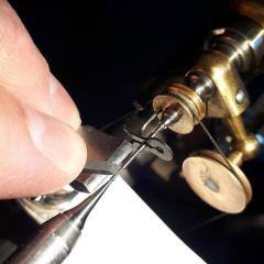
 So I just wanted to say "thank you" again. The angle is the key bit it seems and yes, it did basically just fall, or float, back into position when I got it lined up just right. I had meant to add that now that I see how it goes in, I totally see how it came out in the first place, and that whomever cloned the original movement didn't pay much attention to the fine details around the setting or how it interfaces with the balance cock or the "rings" on the regulator and/or stud carrier arms.
-


Recommended Posts
Join the conversation
You can post now and register later. If you have an account, sign in now to post with your account.
Note: Your post will require moderator approval before it will be visible.