Search the Community
Showing results for tags 'Kentic'.
Found 1 result
-
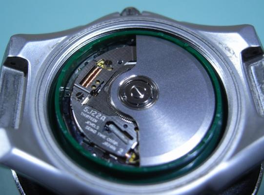
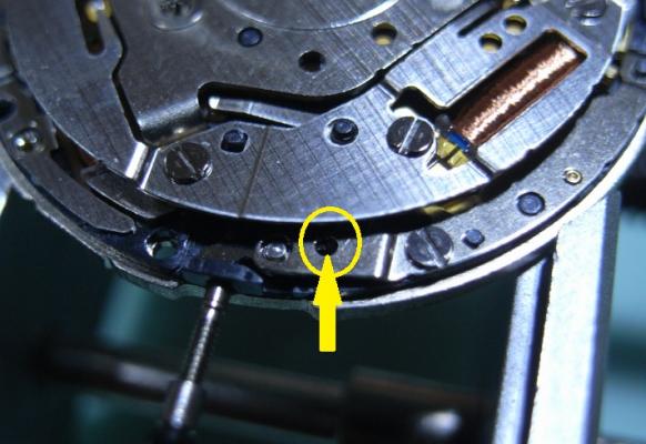
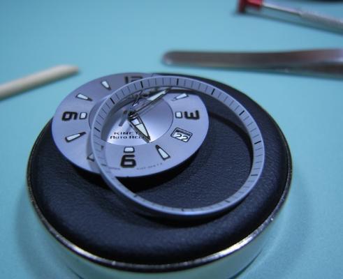
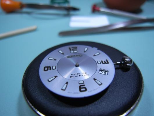
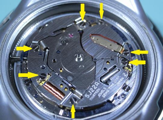
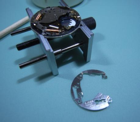
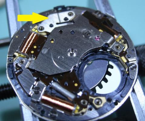
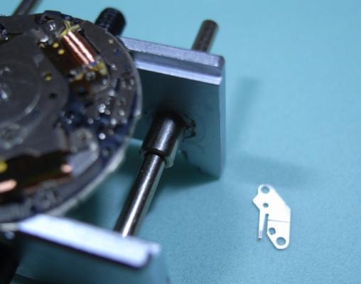
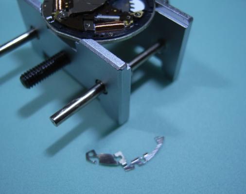
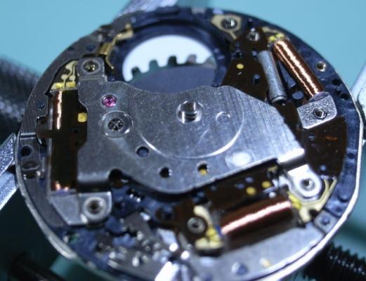
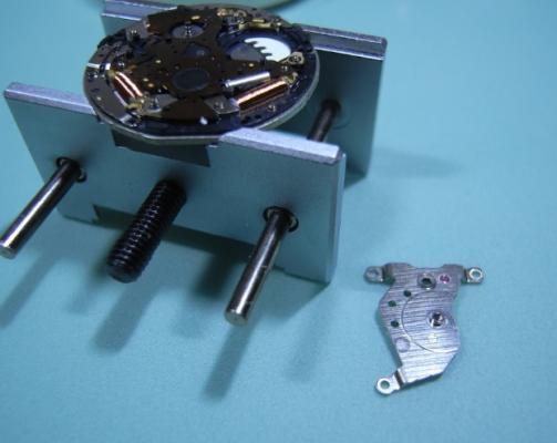
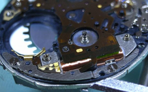
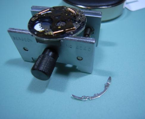
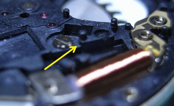
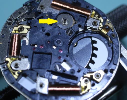
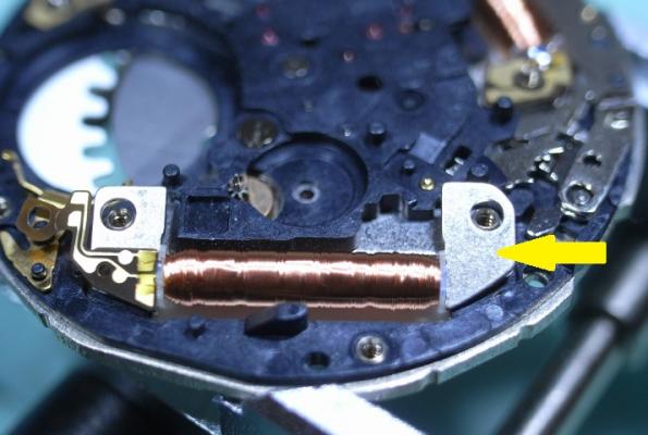
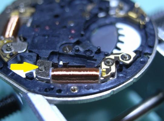
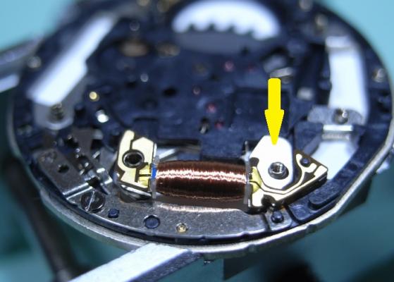
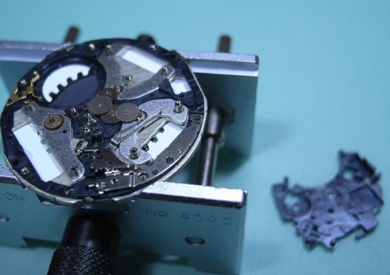
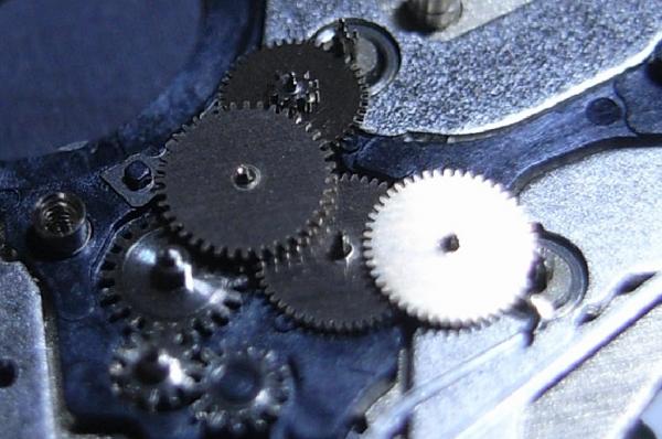
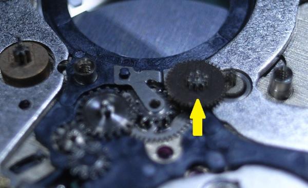
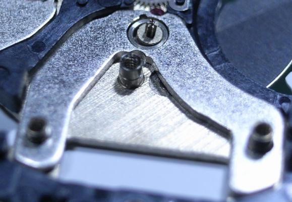
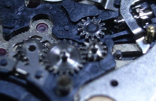
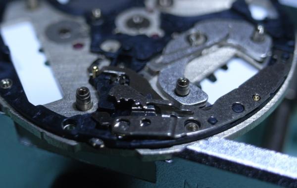
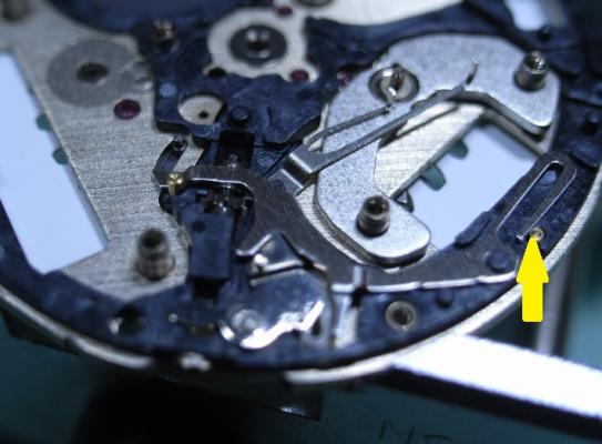
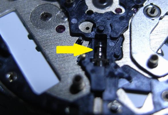
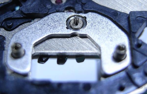
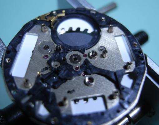
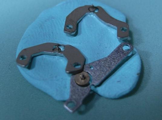
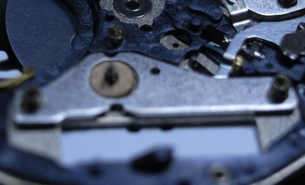
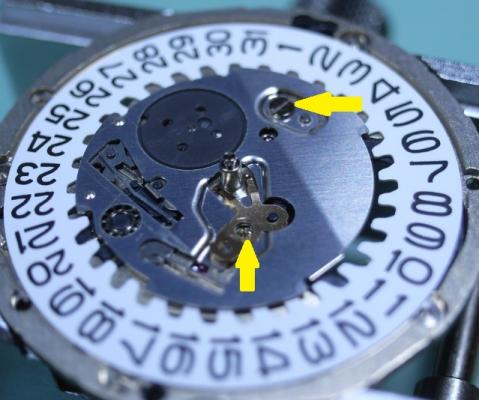
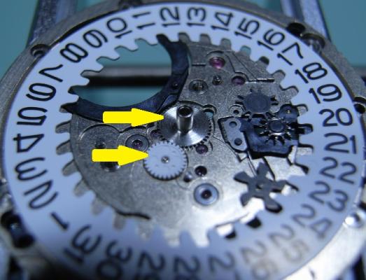
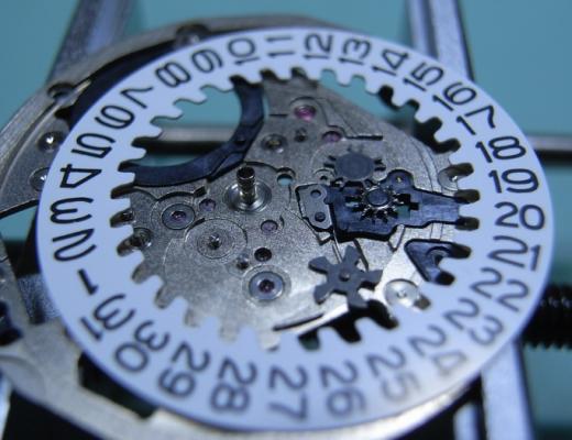
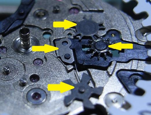
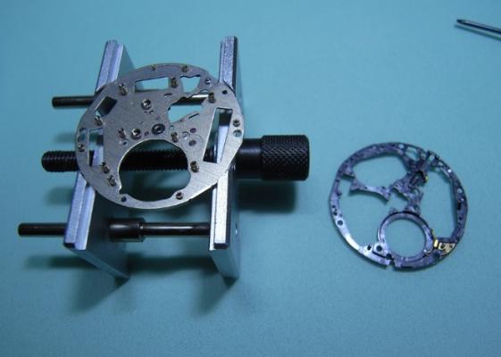
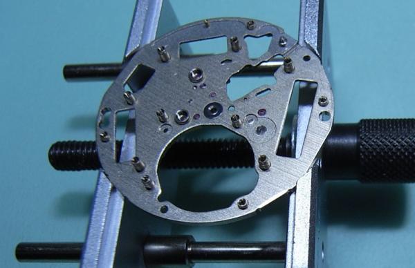
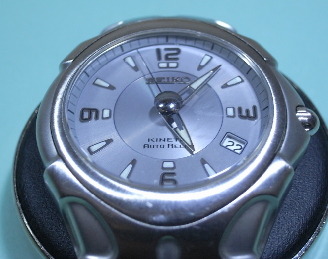
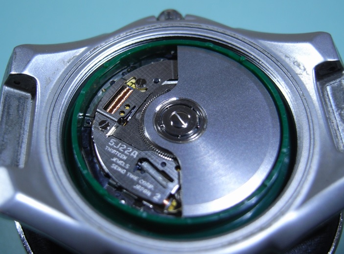
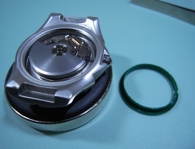
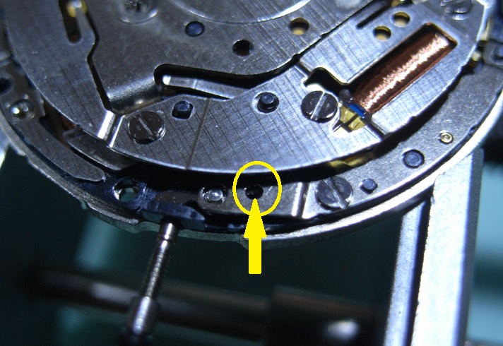
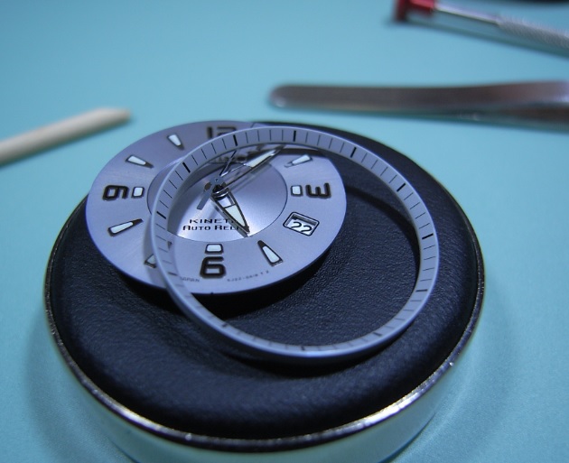
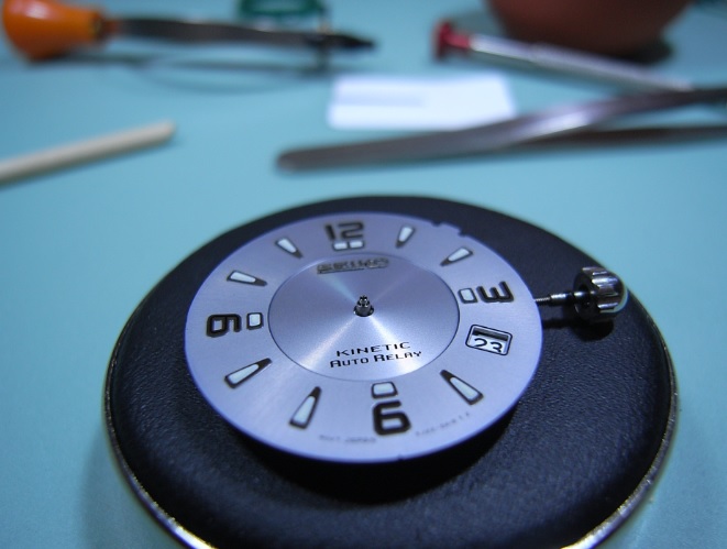
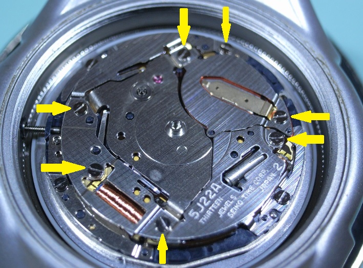
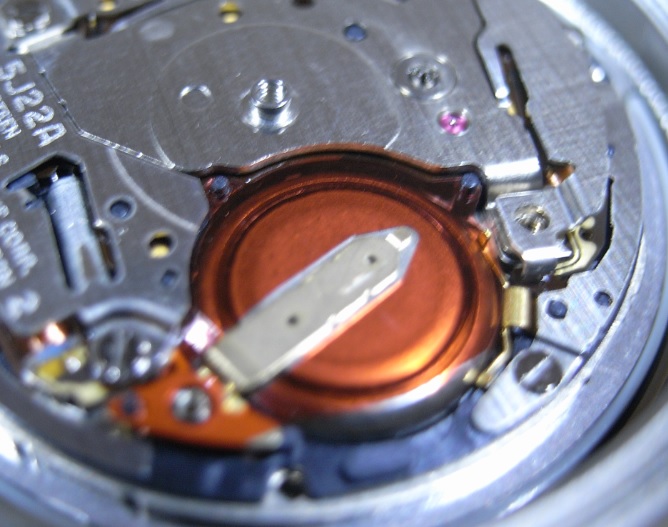
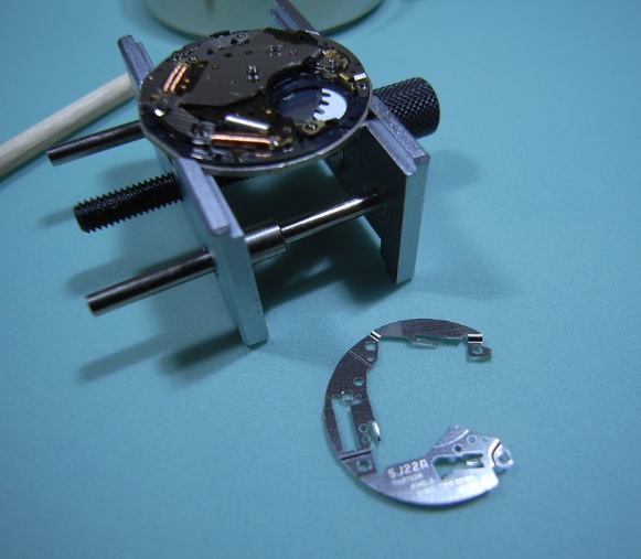
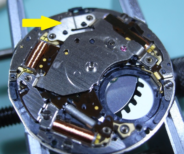
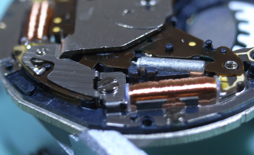
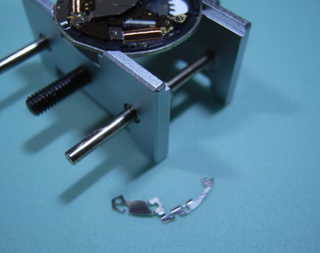
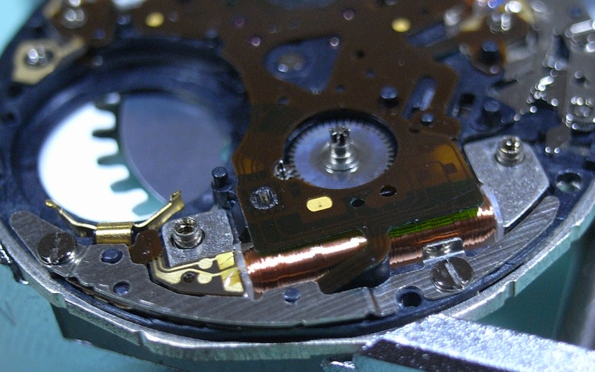
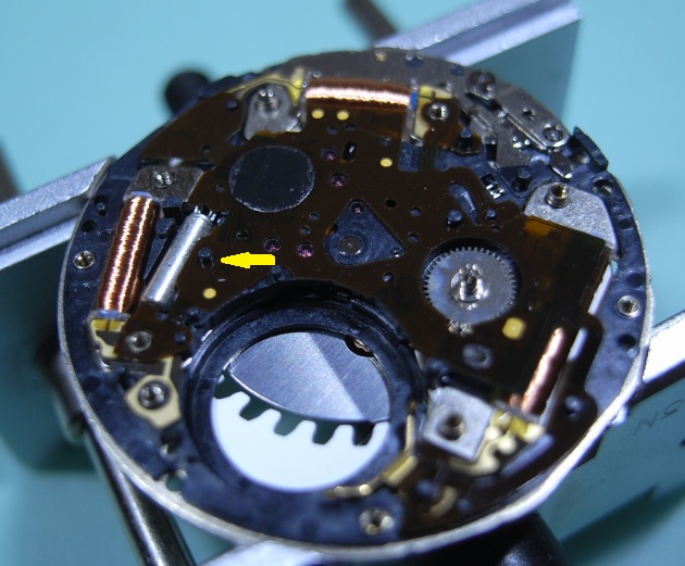
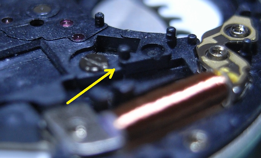
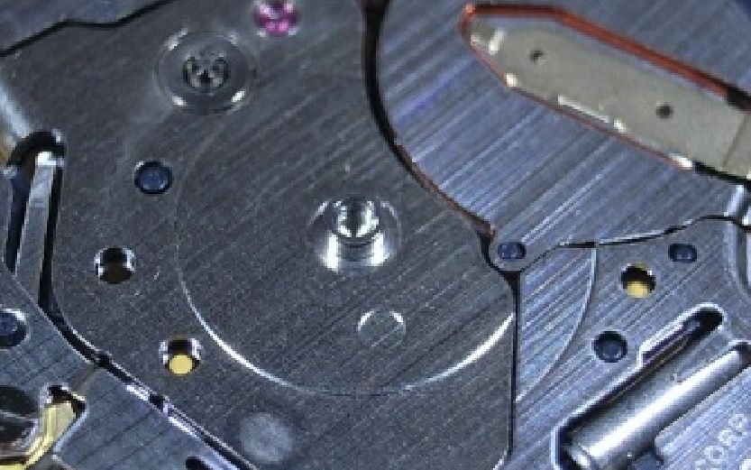
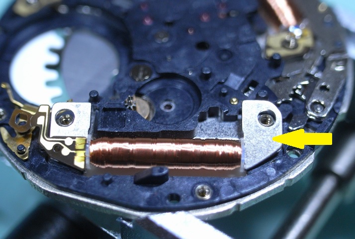
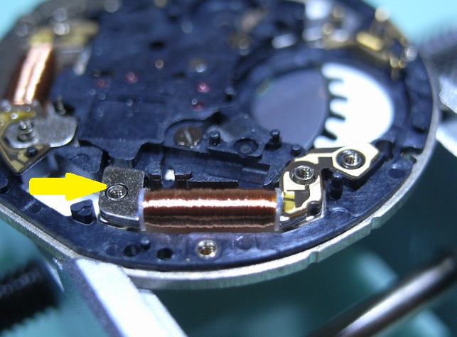
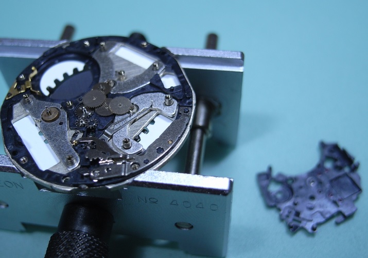
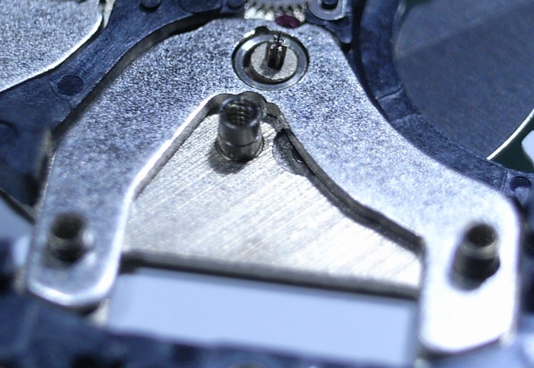
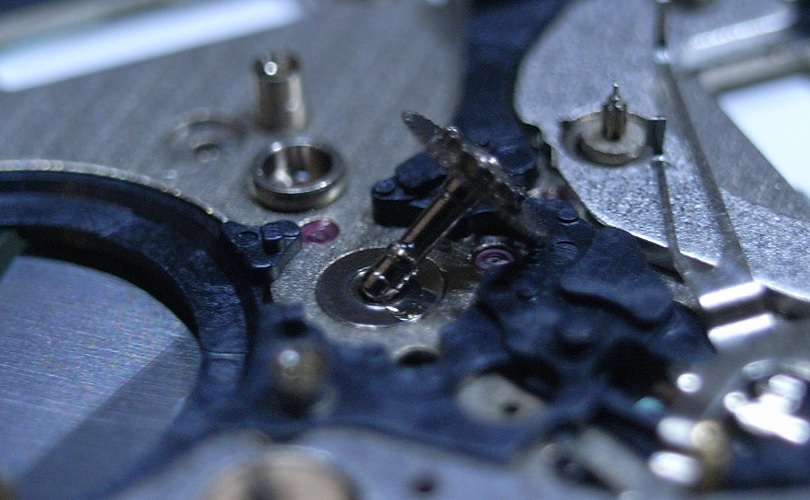
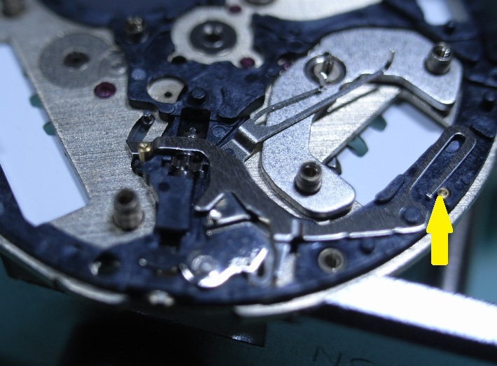
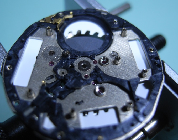
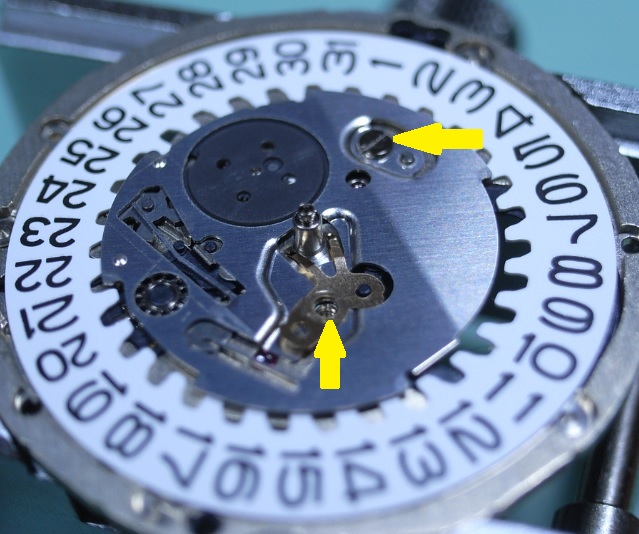
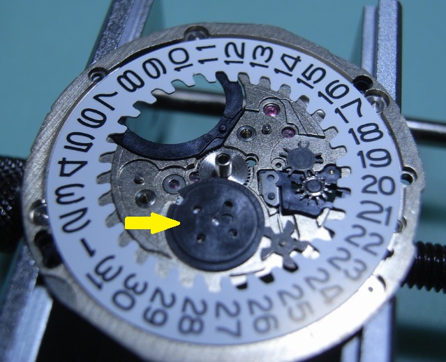
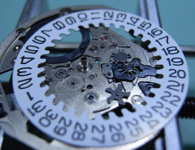
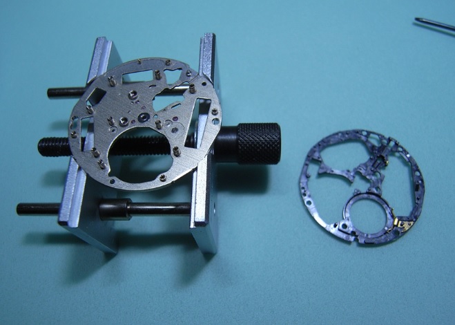
 Seiko 5J22A Complete Service Hunting through my cupboards I found my old Seiko Kentic "Auto Relay" that I purchased sometime in the 90s, when this was the latest cutting edge Quartz Watch on the market offered by Seiko. It's been sitting for over a decade without use, and I decided to really push myself and, with the Lord's assistance, completely strip and service this watch. So I tracked down the Tech Specs, and if you are thinking of embarking on servicing the 5J22 YOU WILL NEED THEM!! :) So here they are: 5J22A.pdf I will be using the part names from this document for this walkthrough, so download and print it out for you own sanity. The parts in this movement are incredibly small, so much so that my camera had trouble focusing on them ... so part names will help you as much as the visuals aids for this service. Once again, I've had no one to guide me on this, so this is the way "I" stripped the movement down, the correct factory procedure may, and probably does, differ from my way ... so I give a warning here: CONTINUE AT YOUR OWN RISK. Disassembly Unscrew the back cover and store the rubber gasket away safely. With a 2.0mm Screwdriver, pry the Location Ring out with the slots provided in the plastic ring. Remove the Oscillating Weight with a 1.20mm Screwdriver ... and this will be the driver you use on all further screws. To remove the Stem, you need to have the Stem push all the way home, to move the Yoke into the correct position so you can depress the lever (Location shown in picture after I removed the movement to make it easier to see the spot where you push) The movement should now come out of the case along with the internal Bezel Ring. Remove the Hands Remove the 7 screws for the Circuit Block Cover A, and the Rechargeable Battery Clamp (Sorry referred to an older pic to so you the location of screws) Remove the Insulator for Rechargeable Battery, and then the Battery itself. Remove Circuit Block Cover A Remove Circuit Block Cover D Reference picture of Circuit Block Cover D Remove Circuit Block Cover B Reference picture of Circuit Block Cover B Remove Oscillating Weight Bridge Reference picture of Oscillating Weight Bridge Remove Circuit Block Cover C Reference picture of Circuit Block Cover C Remove Circuit Block NOTE: The pin with the yellow arrow pointing to it holds onto the Circuit Block very firmly. Be CAREFULLY and GENTLE, as the Circuit Block can be easily damaged. This is the angle of attack that I recommend. Coming in on an angle just in front of the Crystal Unit, and gently push upwards ... and I mean GENTLY. Patience wins the day! Remove the Intermediate Wheel for the Generating Rotor Remove the Generating Coil Block (grasp with tweezers where indicated with yellow arrow) Remove the Second Coil Block (grasp with tweezers where indicated with yellow arrow) Remove the Hour and Minute Coil Block (grasp with tweezers where indicated with yellow arrow) Remove the Train Wheel Bridge Remove the Second Wheel and Pinion, the Third and Fourth Wheel Remove the Intermediate Second Wheel TIP: Next is this first of three sets of Stators and Rotors that make up this Quartz Movement. Be sure to place all the Stators and Rotors into a piece of Rodico for safe keeping. As shown below: THESE PARTS ARE MAGNETIC AND WILL ATTRACT PARTICLES, SO DO NOT PUT INTO THE BASKET FOR CLEANING Remove the Second Stator and Second Rotor Remove the Minute Wheel and Pinion, Intermediate Minute Wheel, and Setting Wheel Remove the Center Wheel and Pinion Remove the Generating Stator and Generating Rotor Remove the Setting Lever Spring Remove the Yoke and Setting Lever Note: Release tension on the Yoke Spring FIRST Remove the Clutch Wheel and the First Intermediate Wheel for Calendar Corrector Remove the Hour and Minute Stator and Hour and Minute Rotor This side of the Main Plate is now finished ... time to flip it over and start on the Calendar Works Remove the two screws indicated and remove the Hour Wheel Guard Spring, and the Date Dial Guard Remove the Intermediate Date Driving Wheel Remove the Intermediate Hour Wheel, and Hour Wheel Remove the Date Dial Remove the Day-Date Corrector Wheel, Second Intermediate Wheel for Calendar Corrector, Date Driving Wheel and Spring Note the position of tension of the Date Driving Wheel Spring (bottom of page 9 in the Tech Specs) Remove the Circuit Block Spacer ... and the disassembly is complete! I started work on this rather late at night and took my time and studied each part before removing, making sure to document everything carefully. So I'll clean the parts and begin reassembly fresh tomorrow. I can see this one is really going to push my abilities, and I'm looking forward to tackling it and uploading the reassembly steps.