Leaderboard


Popular Content
Showing content with the highest reputation on 01/28/23 in all areas
-
I recently retired and decided to re-start the watchmaking hobby I gave up 40 years ago. Having blown the dust off my old lathe and tools, pulled out my large box of movements, parts etc including a box of a dozen or so watches I kept seperate because they triggered my radiation detector, Radium yuck, I decided to look at some forums. There are many but not all are friendly to all, in particular there is a lot of snobbery towards youngster newbie's, yet they are the very people the industry needs as experience watchmakers are retiring or visiting the big cannon pinion in the sky and not being replaced in sufficient numbers. This forum stood out as being friendly to all, in particular the younger newbies that are desperately needed to keep the profession ticking. So how could I not join I have 40 years of dust to blow away.3 points
-
I've used the articulating type at work, and I didn't like them as much. With the long arm, they vibrate. And don't stay as steady as you adjust the focus and magnification. The dual arm design and rotate and slide on the bearings, allowing it to move in the X-Y plane easily, to move the view around the workpiece while the Z axis, and thus the focus, remains constant. The the arm design is free to move in all directions, so it doesn't stay in focus as you move it around as easily. To give you an idea of height, with a 0.5X barlow the vertical distance from the eyepieces to the desk is about 17". 0.5x is the most useful working distance and magnification range.3 points
-
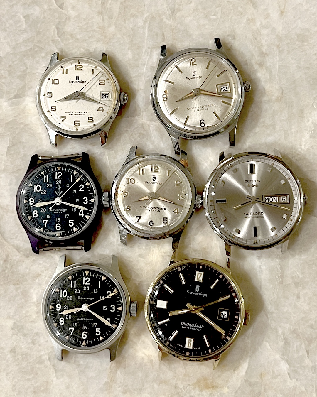
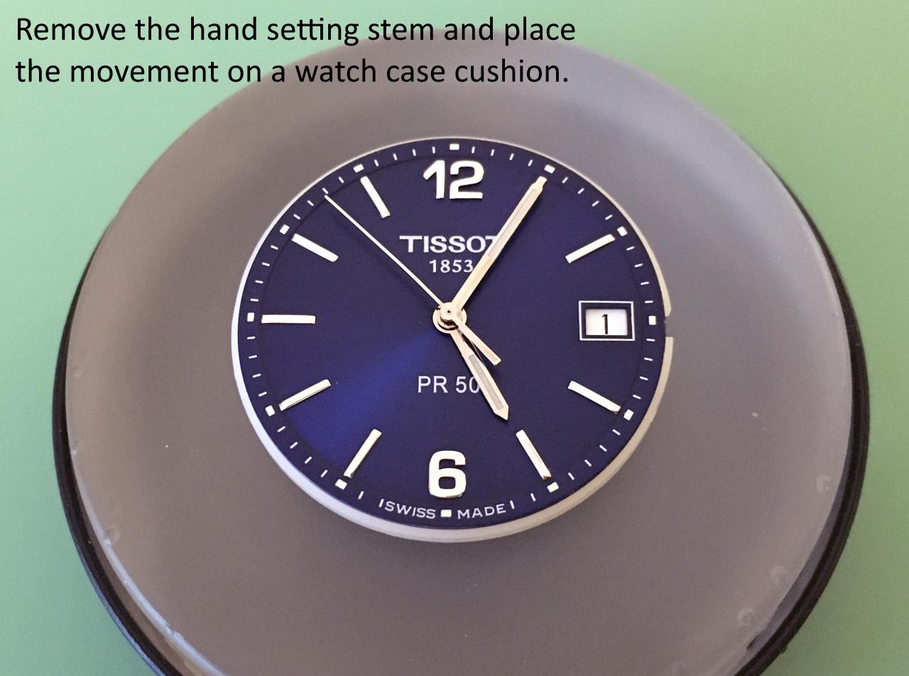
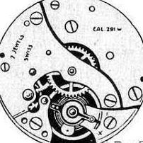
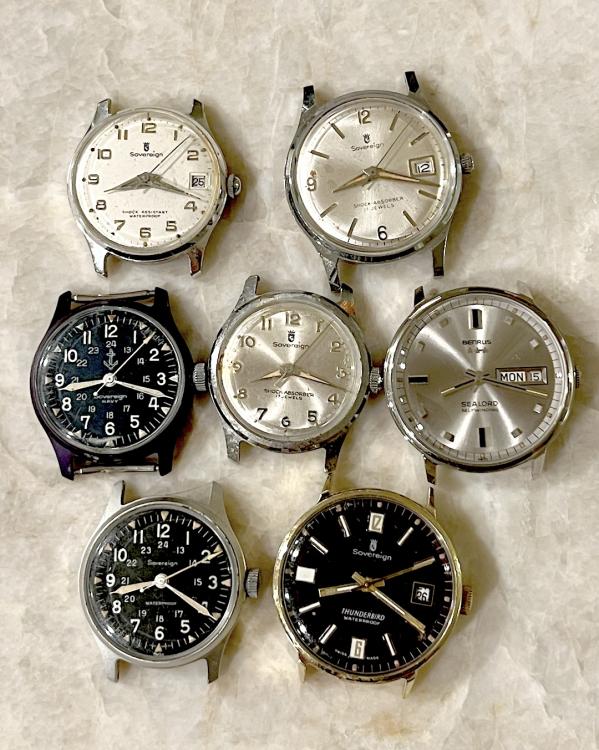
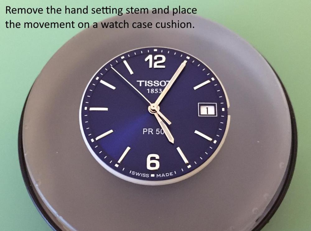
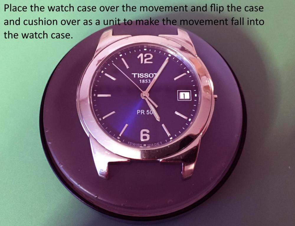
@watchweasol hit the nail on the head, and the giveaway is the time that is showing: 8:18 - see the photo of some demo watch cases with the hands all set the same way. In salesman samples from the Benrus/Belforte/Sovereign group a plastic disk substitutes for the movement. The stem is always just a threaded rod, but the crown can sometimes be salvaged. It's a mixed bag as far as the rest - the hands are usually unusable but the dial may be OK. However, in later versions I've seen sample dials that have had the feet removed as part of the process, so you sometimes get to deal with that even if the face of the dial comes out clean... They weren't ever meant to be used as a source of repair parts, but we do what we can 60 years later!
 2 points
 -
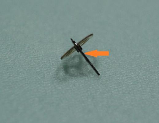
I have straightened bent seconds pivots before. I use a technique that my mentor taught me. First anneal the bent tip with an alcohol flame. Be careful not to heat it till red hot. Then put it on a staking block or any hardened steel surface with the bend facing upwards and tap on it gently with the back end of your tweezers. You don't need a hammer for this. Has worked majority of the time. I've never understood how the seconds pivot can get bent. But I have seen it on many Mumbai specials that I've worked on.2 points
-
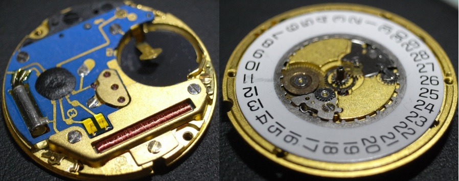
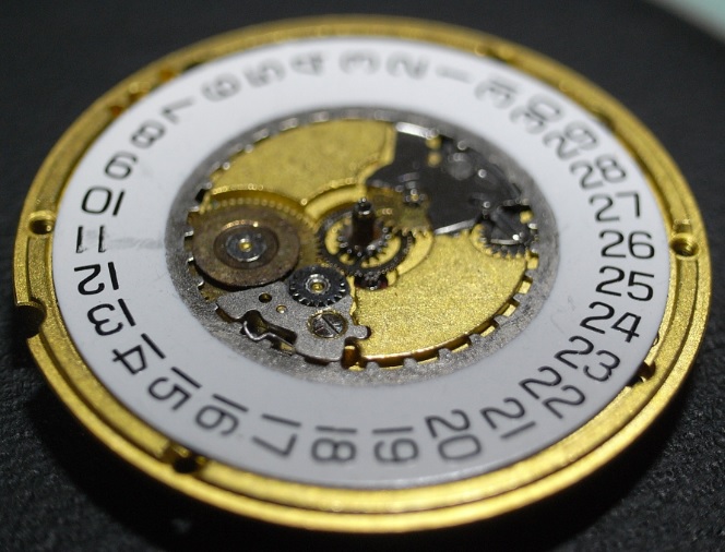
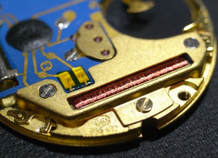
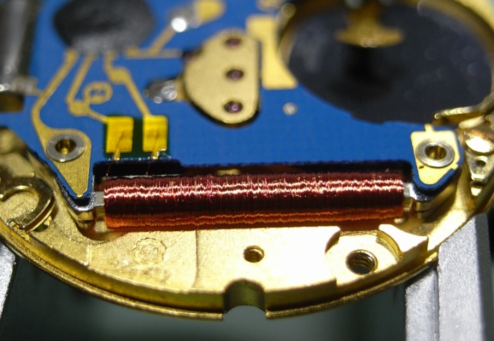
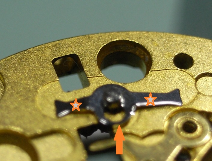
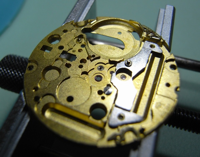
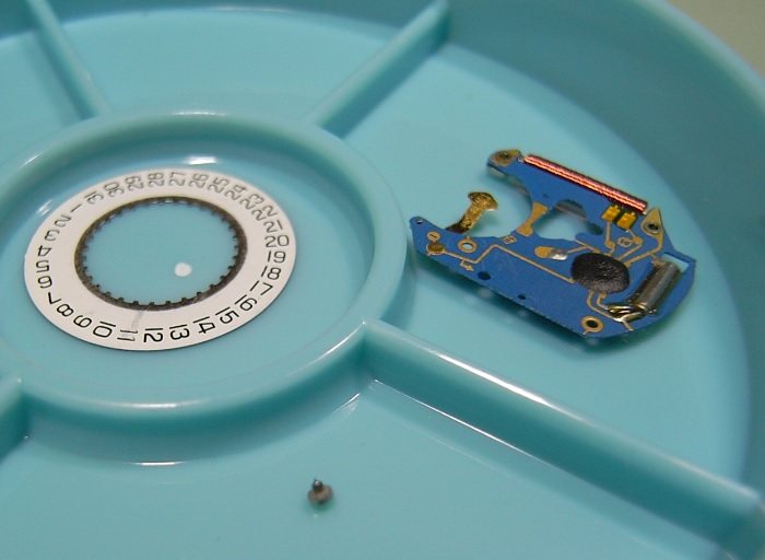
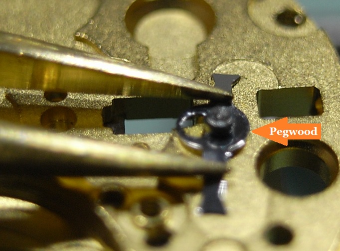
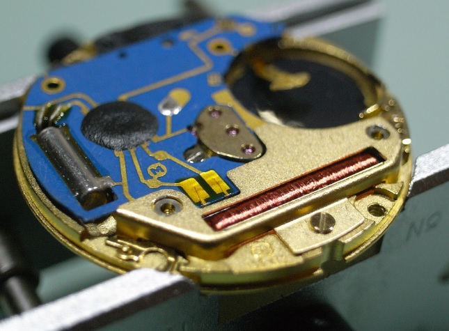
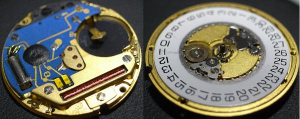
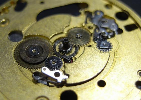
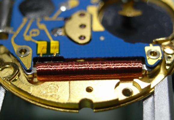
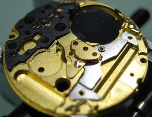
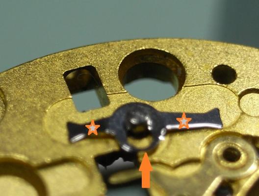
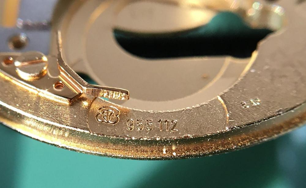
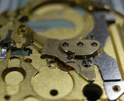
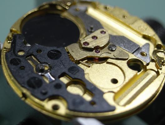
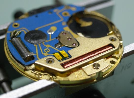
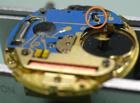
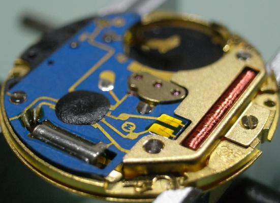
ETA 955 Service Walkthrough "The Workhorse of Highend Quartz" The ETA 955 and 956 Quartz Movements are the most commonly found movement in high-end quartz watches with three hands and a date feature. You will find them in Omega, Tag, and many other brands on the market. For this walkthrough I will be using an 955.412 Movement as my example; but the 956 is so similar to the 955, that this walkthrough will suffice for both. Please note that the numbers after the decimal place only relates to the factory in which the movement was made, so yours could read 955.112, or another factory number ... regardless, the parts are identical and interchangeable. As with all movements, quartz or mechanical, they have a service interval that should be adhered to for longevity of the movement. With quartz movements when the lubrication becomes dried out, or the movement becomes dirty, they will draw more and more current from the battery in order to maintain accurate time keeping. The ETA 955/6, when in optimum condition should draw around 800nA ~ 1.5uA, if the movement is drawing more power than this, a service is required. If a service is not performed, the battery life with decrease markedly, and can go as far as drawing more power from the battery than it was designed for, and damage the battery and cause it to leak and corrode your valuable time piece. Service Manual for the 955/6 Movement CT_956412_FDE_493024_06.pdf.PDF Disassembly Remove the two Date Wheel Keepers. I always start with the one holding the Date Jumper Spring in place. Sometimes the Date Jumper Spring can ping out of place, so be careful when removing the keeper plate above it. Here is a reference photo in case it moves before you see how it's properly seated. Next remove the Keepers and Date Wheel. Then remove the Date Jumper Spring, Motion and Calendar Work. This will leave only the Keyless Work; remove the Yoke and the Sliding Pinion only. We need to flip the movement over, and disassemble the IC Board before we can remove the rest of the Keyless Work. With the movement flipped over, remove the 3 screws holding the Coil Protector. Note for re-assembly the Gold Screw in the centre. Now that the Coil Protector is removed, GREAT care must be taken not to damage the exposed fine windings of the Coil. Then to remove the IC Board, simply remove the 2 remaining screws that hold it. Do this slowly and carefully, as you do not want to slip off the screw and damage this delicate circuit. The same level of care needs to be taken when removing the IC Board from the Main Plate. Take your time and carefully lift it off and store it immediately out of harms way. Next remove the black Insulator Block, and Battery Insulator. This will expose the Setting Lever Spring Clip, which will enable you to remove the rest of the Keyless Work. To remove the Setting Lever Spring Clip, place both points of your tweezers on the locations where I've placed the stars and gently push down on the spring. Then with a piece of Pegwood, push the spring in the direction of the arrow until it moves to the larger opening slot. This will now allow the Setting Lever to be removed, along with the rest of the Keyless Work. Next remove the Stop Lever and Switch, and remove the one screw holding the Train Bridge in place. Then carefully remove the Gear Train and the Rotor. The movement is now completely stripped and ready for inspection and cleaning. There are some parts that you do not place in the parts cleaner, they are as follows: Date Ring Rotor IC Board The rest should be demagnetized prior to cleaning to avoid any metal particles in your cleaning solution from sticking to your parts. When cleaning I also including the Insulator Block, and Battery Insulator in the basket, normal watch cleaning solutions do not harm these items and it is essential they are completely clean to provide the best insulation possible. The Rotor should be cleaned by use of Rodico. As you can see from the picture below, it's surprising the dirt and old oil this will remove ... and it is sufficient cleaning for the Rotor. I hope this has been a help to you, and I will post the assembly procedure later today, if time permits.


 1 point
 -
For flux you could use the one NorthridgeFix recommends (Amtech) IIRC, but don't get it from eBay or Amazon almost if not all the Amtech on those platforms is counterfeit. Have a look on YouTube there are quite a few reviews on the different types of smd fluxes.1 point
-
Should be „acid free“ and low viscosity.1 point
-
You realy don't need a walkthrough, tear one apart take as many pix you have the patiance for, upon reassembly if you forget which part goes where, you have another movement to tear apart and see for yourself. Thats how I started, back then I didn't know data sheets and diagrams of movements exist.1 point
-
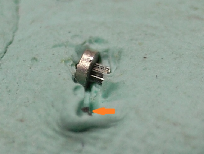
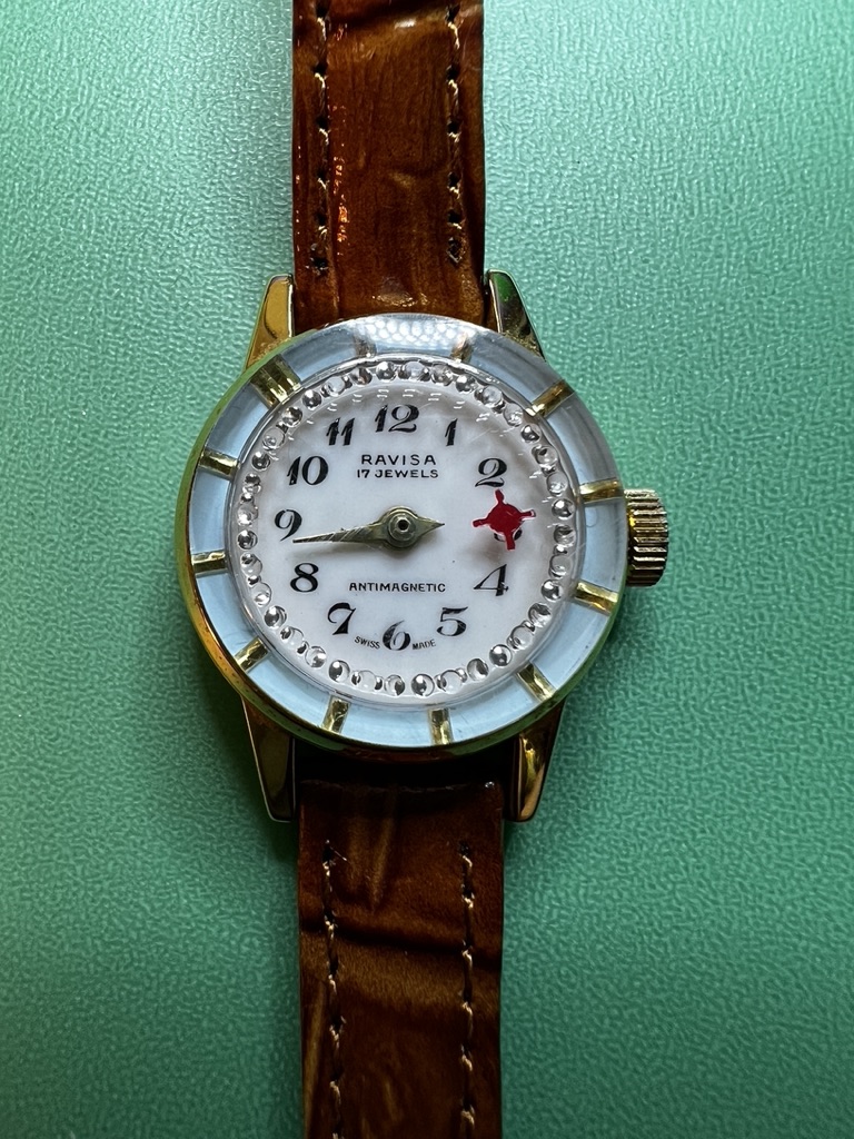
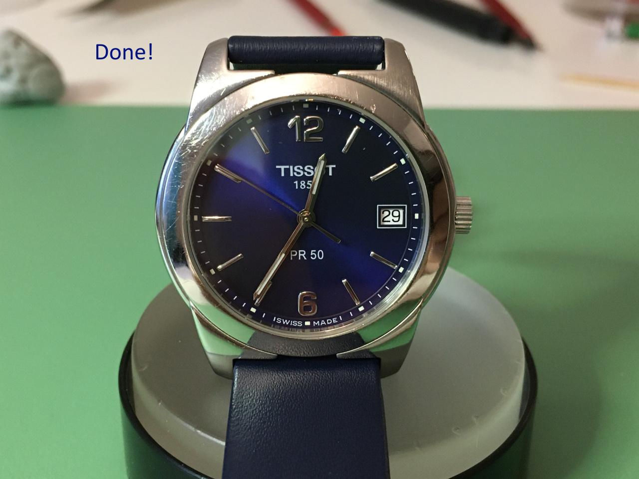
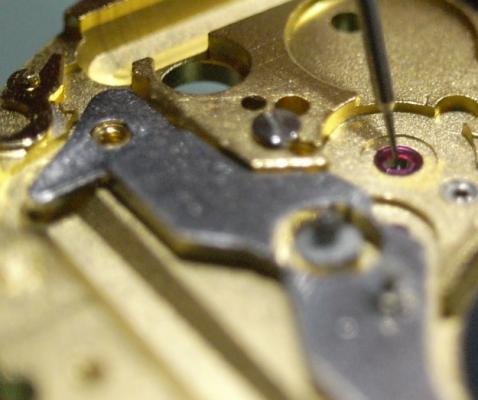
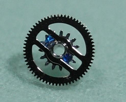
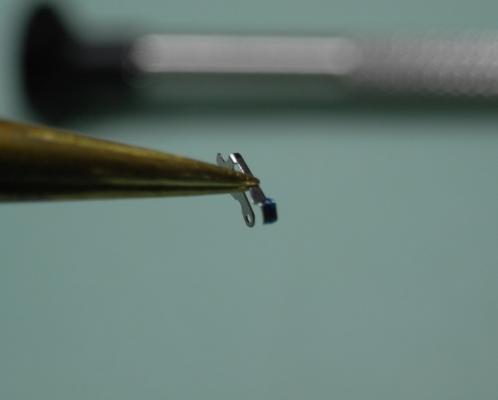
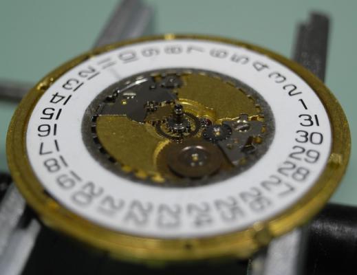
Thank you @HectorLooi. This is more excellent information. This watch doesn't has a center seconds "hand" but instead it has a floating disk which rotates under the crystal, creating a glittering effect on the edge of the watch (see picture below). It is certainly possible that when i removed the disk, i bent the pin.
 1 point
 -
Thanks for the comprehensive and detailed description of the problem and the events leading up to it. My guess is you are on the right track with your thoughts about the regulating pins. If the gap is wide and your hairspring is way off centre, i e. touching one of the pins at rest, then the rate will increase as amplitude falls off. A 20x loupe should be good enough to check this, but finding the right viewing angle and illumination can be awkward.1 point
-
Sounds like you have a mismatched balance/hairspring? I had a case like that on a vintage piece for a big manufacturer. Even they don't have spare parts for this caliber; they sent the watch with a bare balance and a bare spring, said do what you can. Solid balance, luckily the rate was too slow, I think I had to put about 5 opposing hole pairs (10 holes) to get it to rate. It was a pain, as even though I did it with a precision machine, you never really know how much you took and 0.01mm more or less deep will throw the poise off. So it was drill, check rate and dynamic poise, drill, check rate and dynamic poise, again and again. But it did work, and the watch timed within spec (I think 15 seconds delta in 6 positions). That looks like a nickel balance, should drill fine with high speed steel (normal) drills. Glucydur really does need carbide.1 point
-
You shouldn't handle the brass parts after cleaning this will cause the parts to tarnish quick. To prevent tarnish you could always chalk brush the parts. What did you use to clean the movement?1 point
-
It depends upon who you ask and which discussion group you're asking. Then on a modern balance wheel like what you have there isn't really a procedure. As normally wouldn't have to do what you're asking to do. Usually the balance wheels are relatively hard so I would use a carbide drill. Then do the same as they did when their poising just cut the rim on the underside no one will see what you ever did.1 point
-
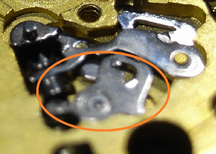
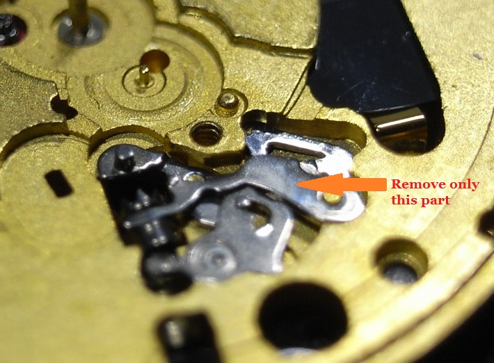
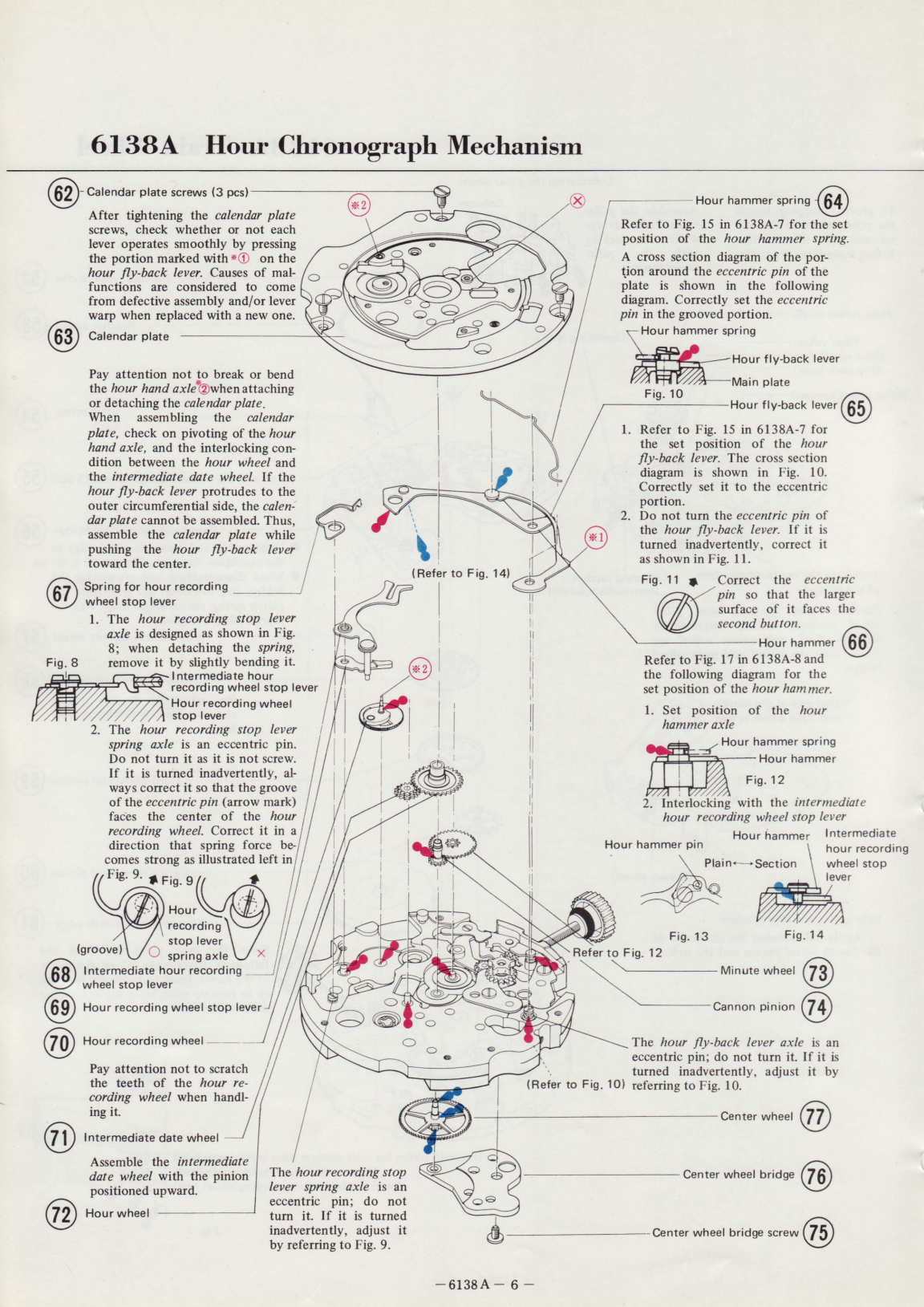
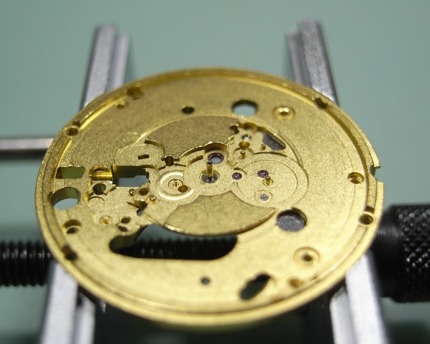
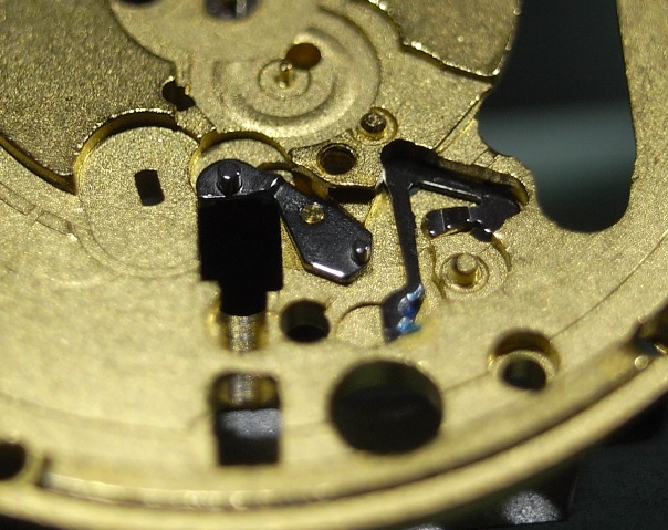
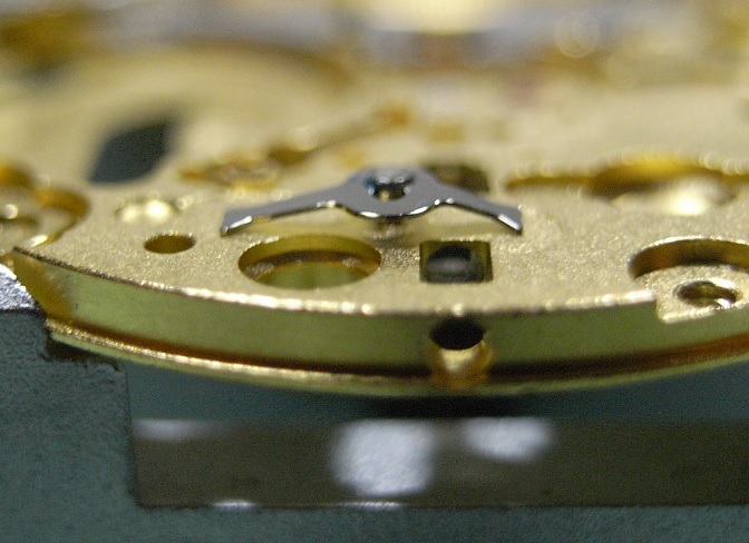
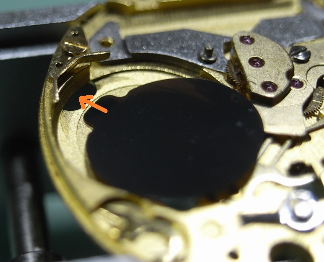
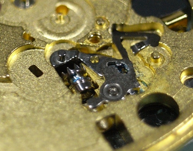
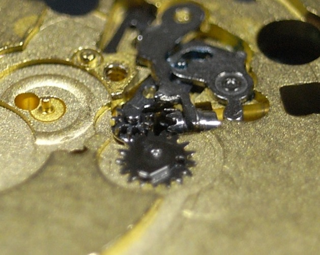
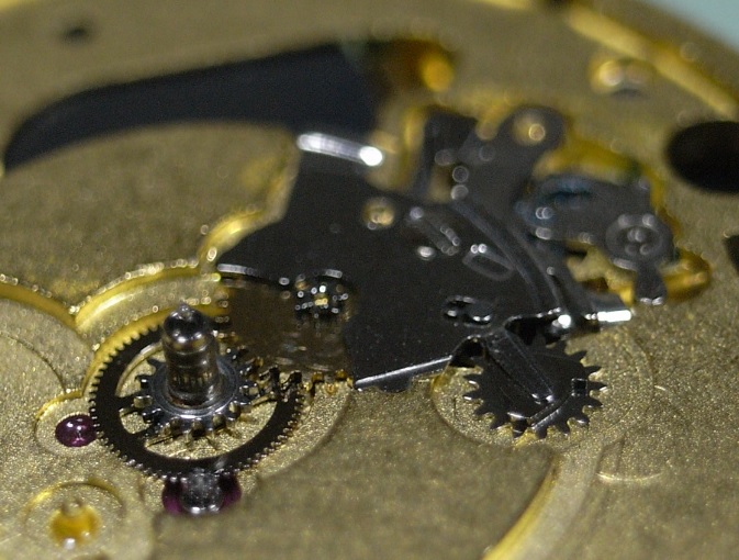
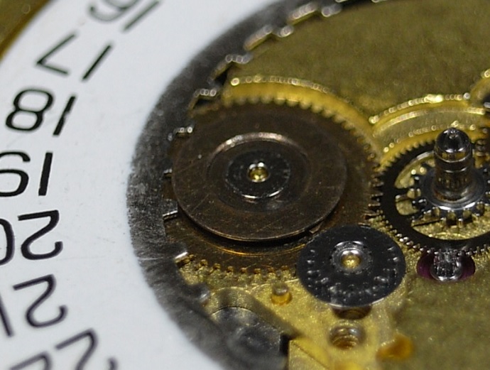
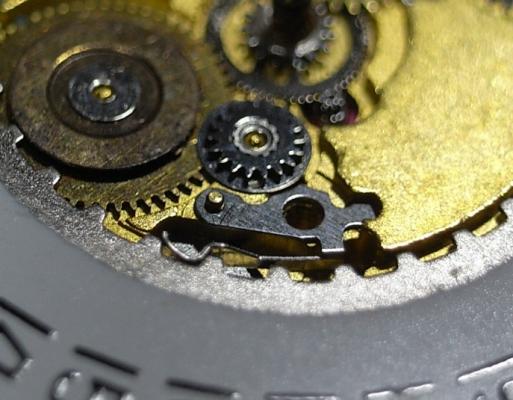
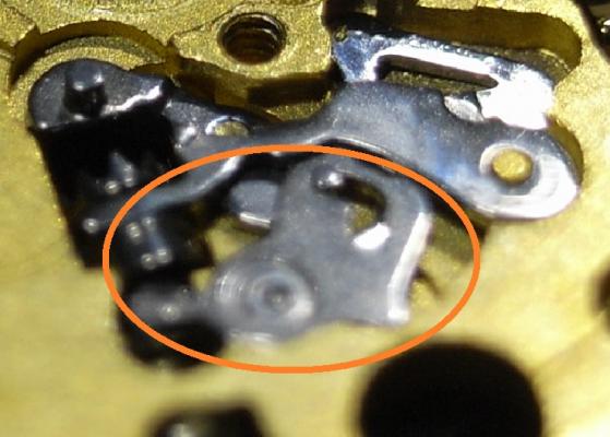
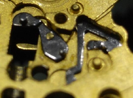
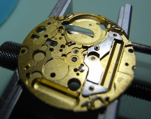
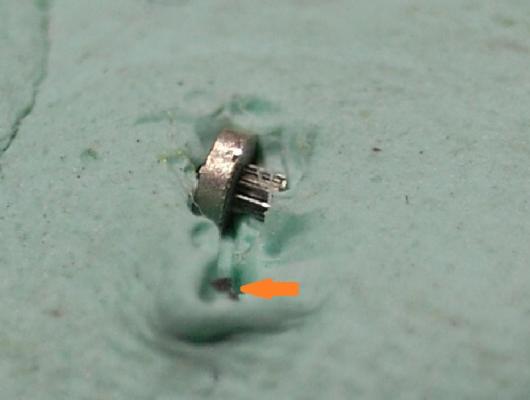
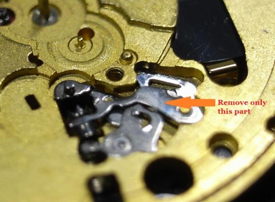
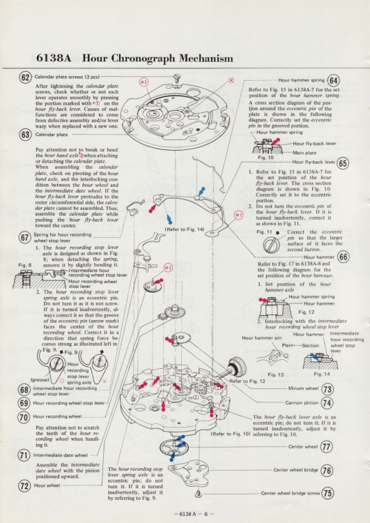
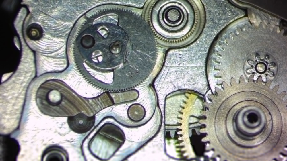
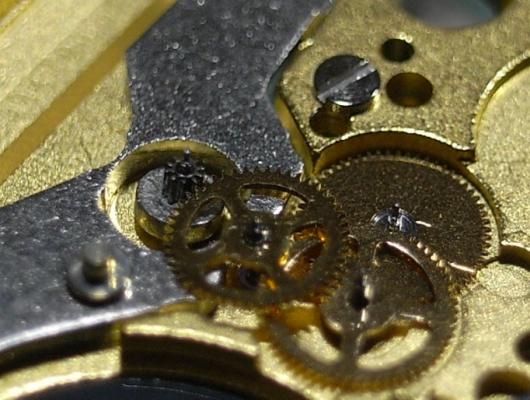
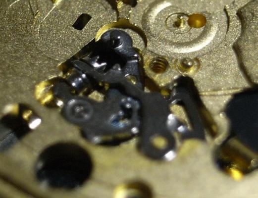
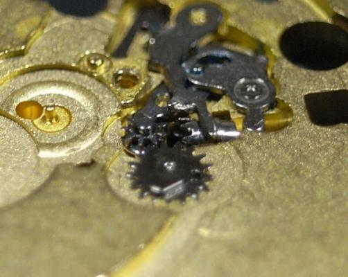
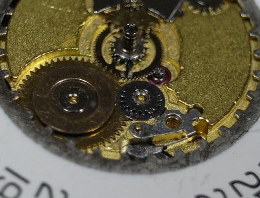
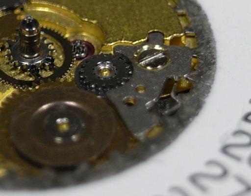
Couple of potential causes I'd think: 1. The spring for the hour recording wheel stop lever has come dislodged, broken, or the eccentric pin has been turned (see Fig. 9 in diagram below), causing it to not apply the correct amount of tension to the stop lever 2. The stop lever has slid under the hour recording wheel (I've seen this on two 6138's I've worked on), although this would probably cause the wheel to not function at all rather than always run. There's really only one way to find out though, and that's to take it apart and have a look. Thankfully you can check the brake without having to remove the front chrono plate. Pull the dial and hands off, remove calendar works, and there's a window that shows you the hour recording wheel and the stop lever meeting together. Here's one I recently came across where the stop lever was on the underside of the wheel (probably not your issue, but you can check): It should sit like this:
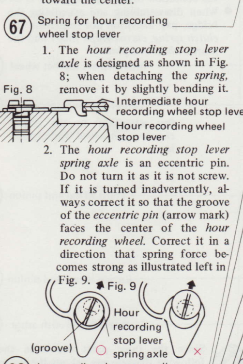
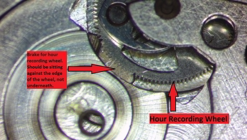
 1 point
 -
Welcome @BigSteveUK Your remark sounds somewhat familiar. I'm not quite there as far as retirement goes, but I picked this hobby back up after a very long time. There is a long and somewhat rambling (and occasionally informative) thread about my antics here. Strangely the thumbnail picture for the thread is someone else's watch desk, not mine. @JerseyMo I suspect its yours, since there is quite a lot of Timex stuff evident. Watch snobbery isn't my strong suit. I'm more a "that's an interesting mechanism/style/quirk/whatever" kind of person, and as a result I have some very strange and quirky stuff in the collection. I suspect very little of it would interest a real "Watch Snob", since none of it would command a particularly high price.1 point
-
The alloy in modern springs (Nivaflex) is precipitation hardened over a period of a couple of hours at around 500C in a vacuum oven. You won't really get any hardness by heating to red and quenching, like with high carbon steel. In fact the annealing process is to heat to 1000-1100C (which would be red hot) and rapid cool, i.e. quench. It should be totally fine though annealed at the center; after the first turn of wind it's held in place on the arbor by the further wraps of spring, and it's still plenty strong enough to hold onto the hook. That small length not being "springy" will have no effect on performance.1 point
-
Yes, I also use an Amscope goose neck LED. Even with this light I still need to change the exposure when I zoom in. I tend to have it at 0 to +8 when fully zoomed out and around +13 when fully zoomed in. It did! the washer popped right off. Unfortunately, where the hour hand was sitting, the lume from the hand had fused to the dial and left a blob of hardened lume on the dial. I was able to remove it with some q-tips and soapy water but it left a discoloration on the dial, which is a bummer as it pretty much defeats the purpose of me getting a NOS dial. Oh well.1 point
-
Interesting idea that like attracts like. Personally when I'm not at my workbench, I'm supporting and working with people who have suffered ABI's. Purley on a voluntary basis as I enjoyed helping people in the community who need support. So I guess I must be the exception to the rule you proposed.1 point
-
I got one of these JDM linked to in a post on page 6. It cost 20 quid off ebay it came with 8 plastic dies, made in India it's a solid bit of kit with no flex what so ever, made from cast iron with a threaded steel shaft, it as an unthreaded pin on the base and a threaded M6 pin on the shaft the die screws onto, the base and shaft pins were in line spot on straight, i thought they maybe off straight like some of the Chinese press's. I first tested it with the plastic dies that came with it, the threads are plastic so screwed on ok and looked straight and level, the gap was even between the upper and lower dies all ok until i had a go at screwing on a plastic die that has a threaded M6 brass insert the ones that came with cheap blue lever press, i tried a couple of different ones and M6 nut just wouldn't screw on, i don't know if the thread was damaged or not cut right, a couple of turns with an M6 thread cutting die fixed the problem, the dies and nut now screw on ok. For 20 quid this is a good press with only one little fault on the one i received, i don't think you can get a better press for this price they probably could sell it for twice the price. When i had ago at fitting a crystal it pressed the crystal in with ease no effort at all compared to the Chinese lever type press that i've used a couple of times it took effort to get the crystal in with the blue lever one. In future i'll use the lever press for removing old crystals and the screw press for fitting the new ones. I think i might order a set of 25 aluminum dies of ali then i've got both plastic and aluminium die set. The press is sold on ebay as a watch case back closer press not sure why it's not sold as a crystal press but will do both.
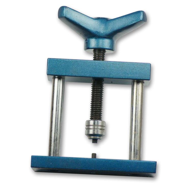 1 point
 -
Heyo, looking at Jules Borel parts list for that movement/case they reference an alternate code for the crystal XAG 311.649 with a link to purchase it here: http://www.julesborel.com/s.nl/it.A/id.20940/.f Looks like it's yellow though? I'm not sure. Maybe you can contact them and find out what other options there are.1 point
-
That's weird. No idea personally but I bet you'll figure it out quick once you start reassembly.1 point
-
ETA Calibre 955.112 Assembly


 1 point
 -
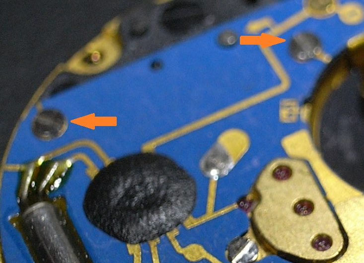
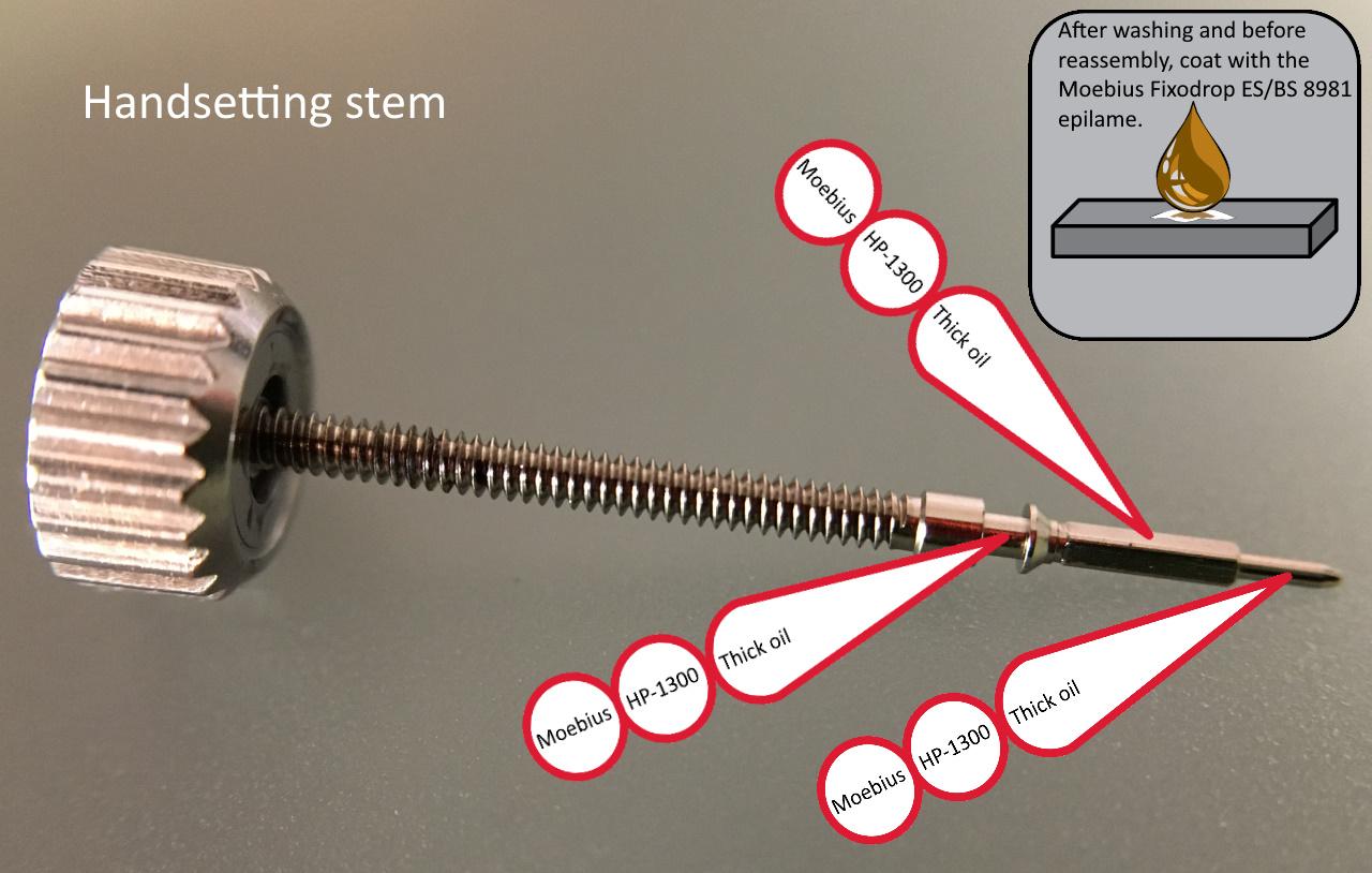
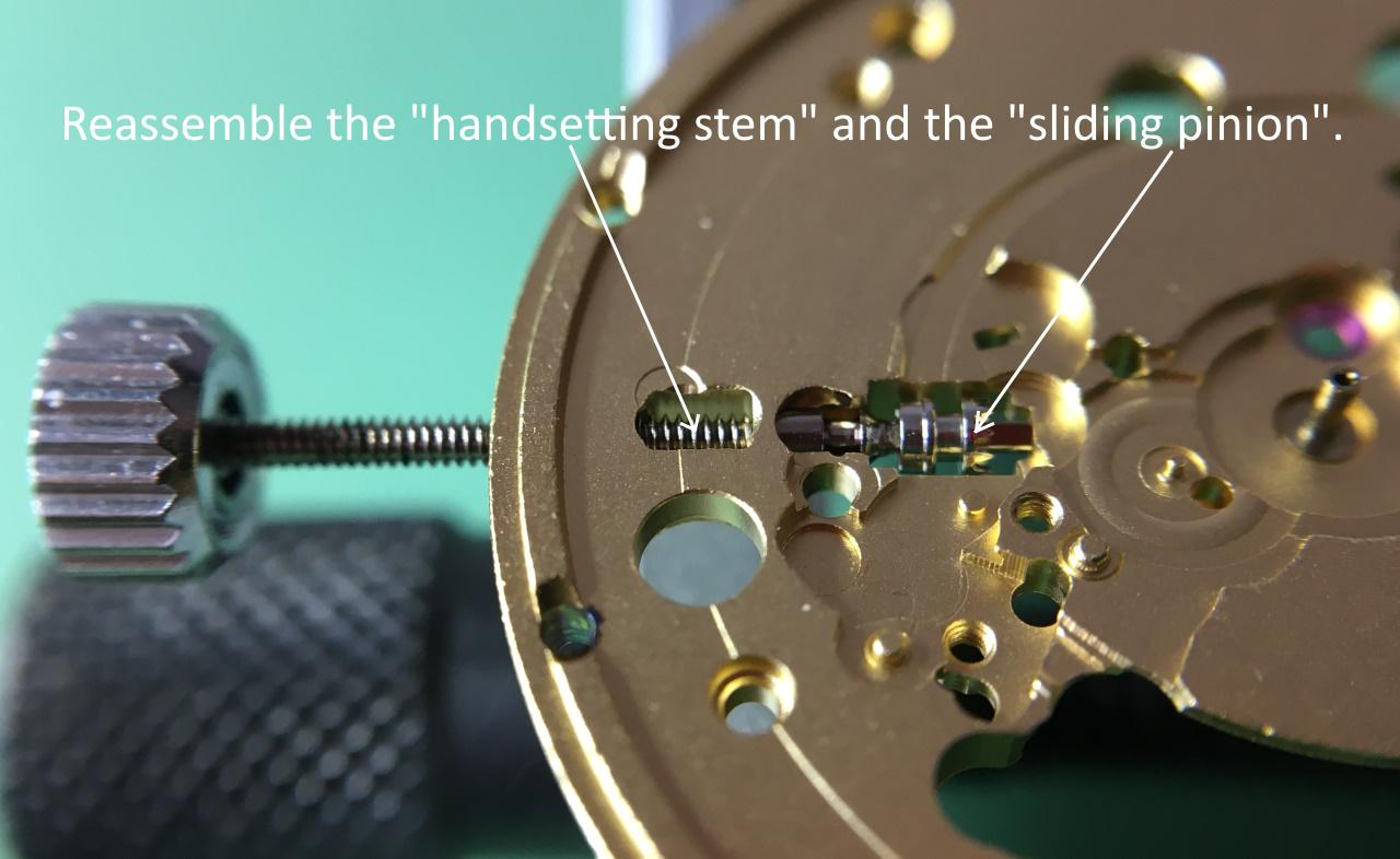
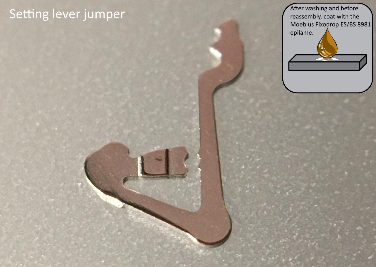
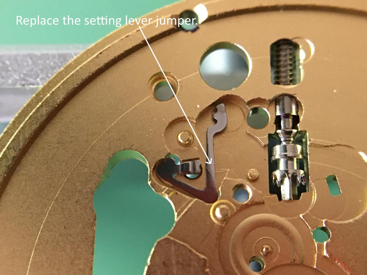
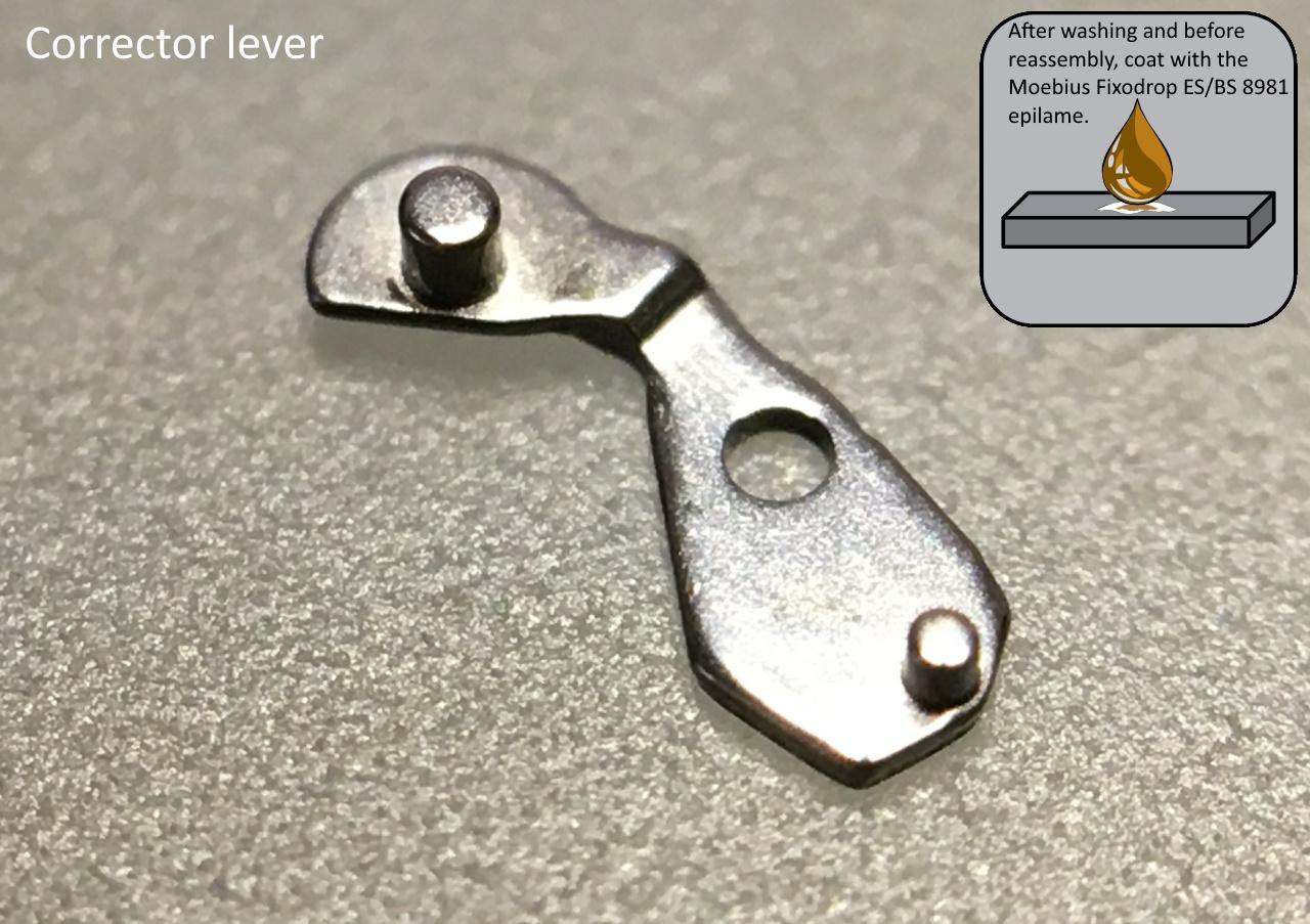
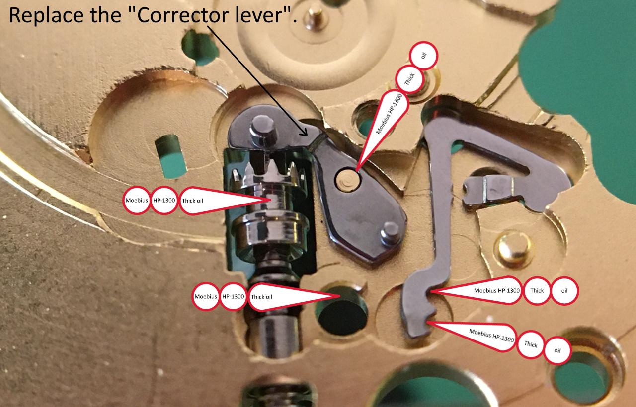
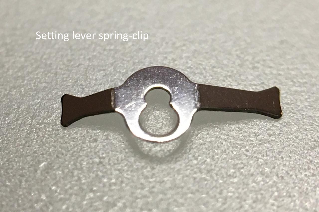
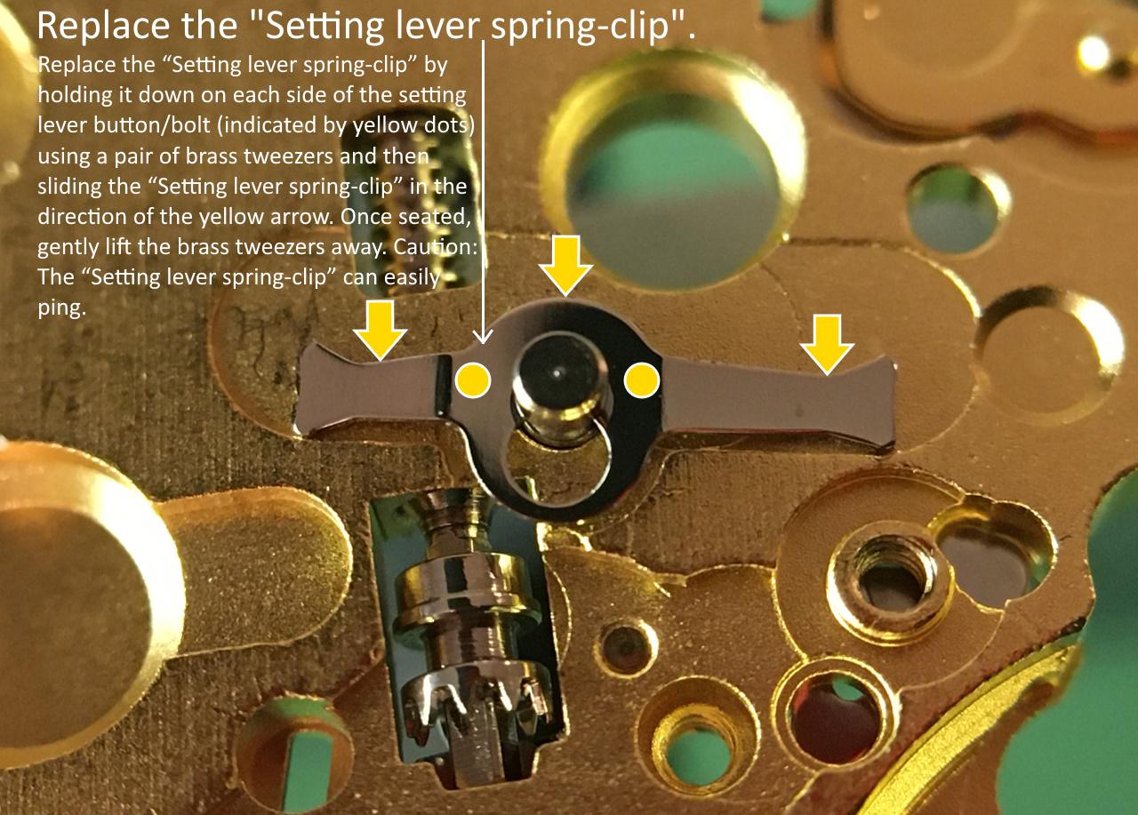
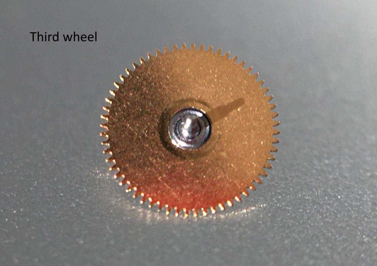
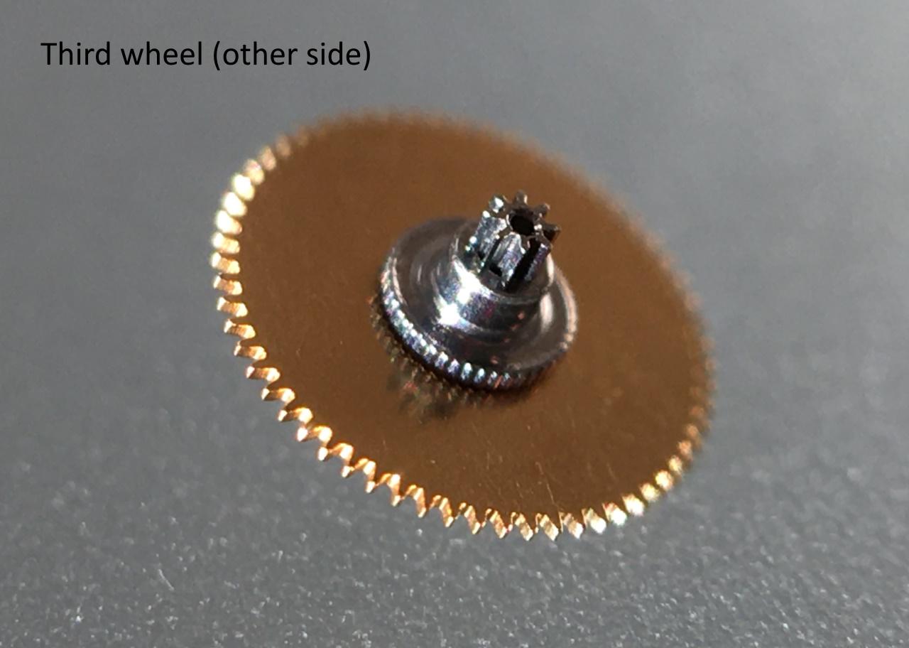
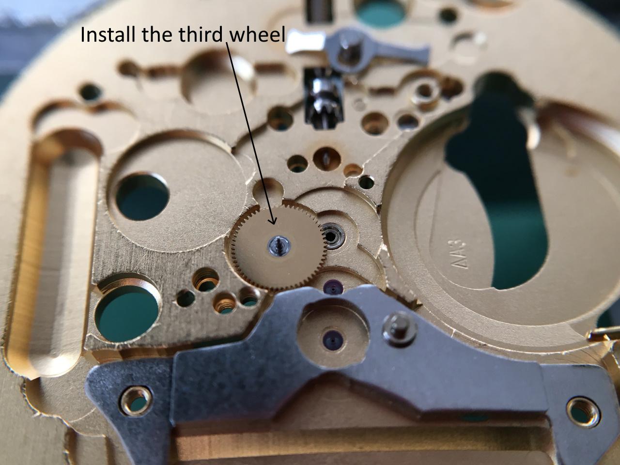
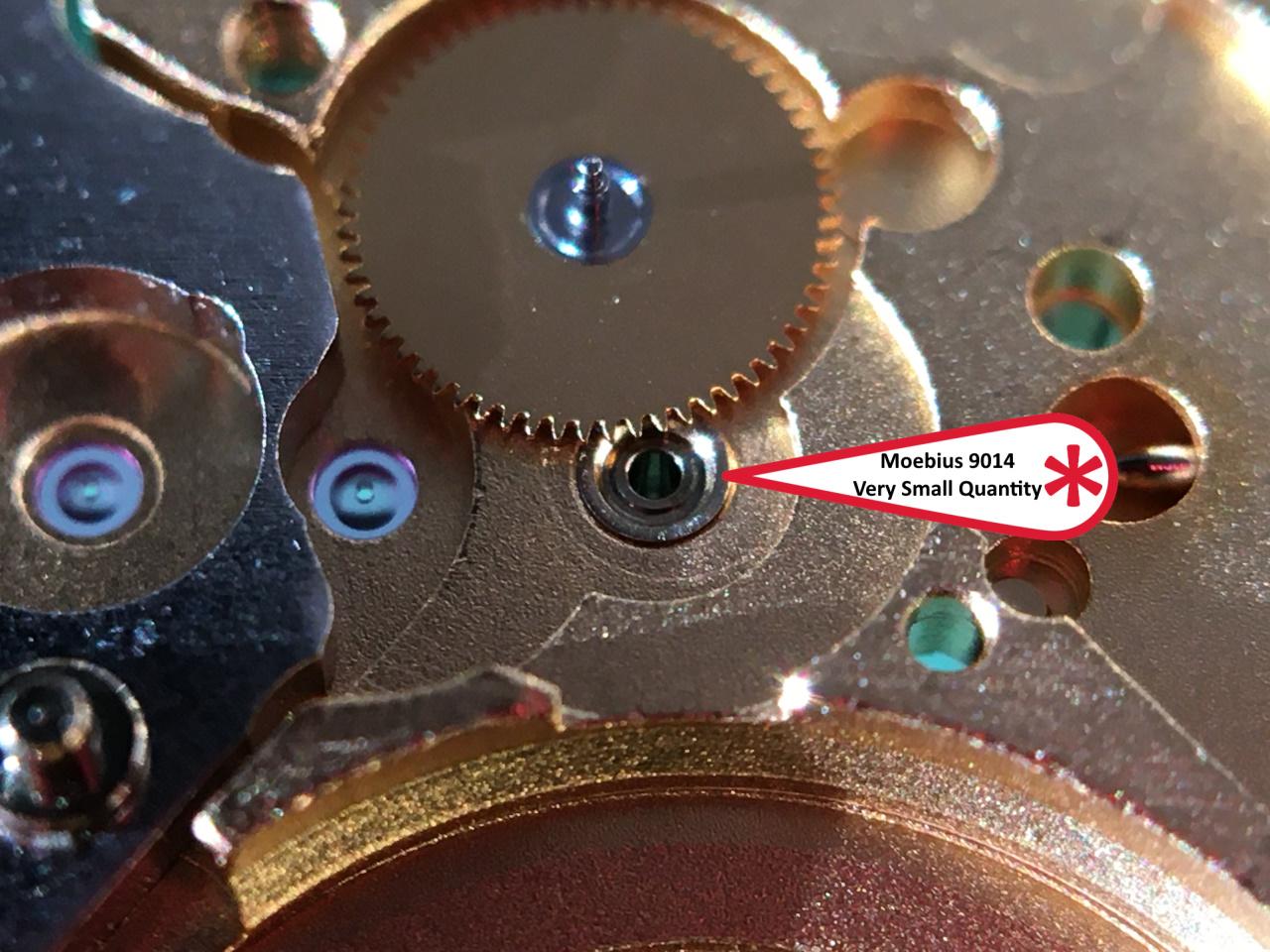
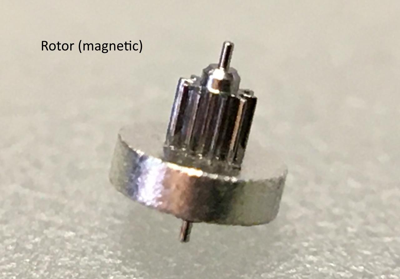
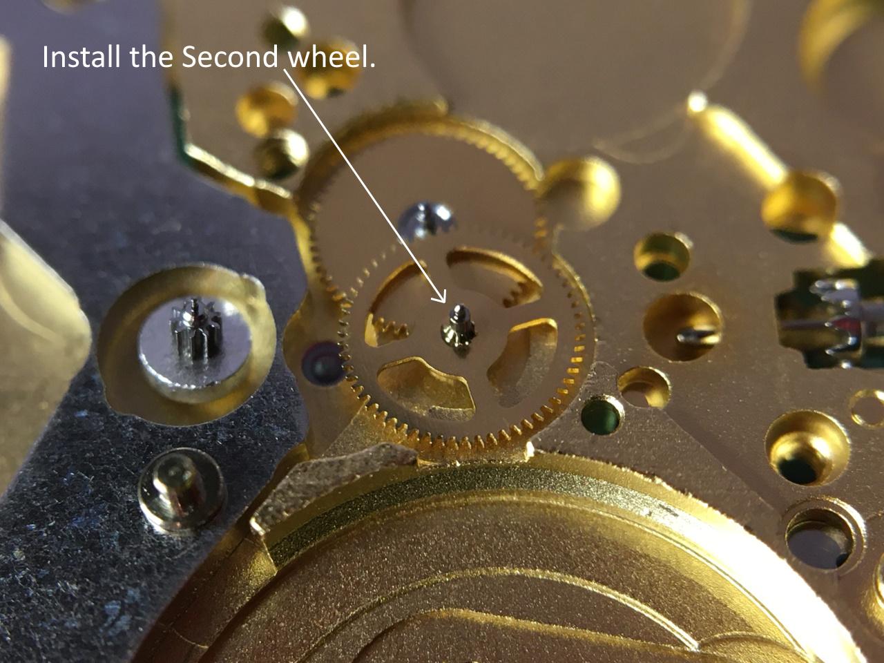
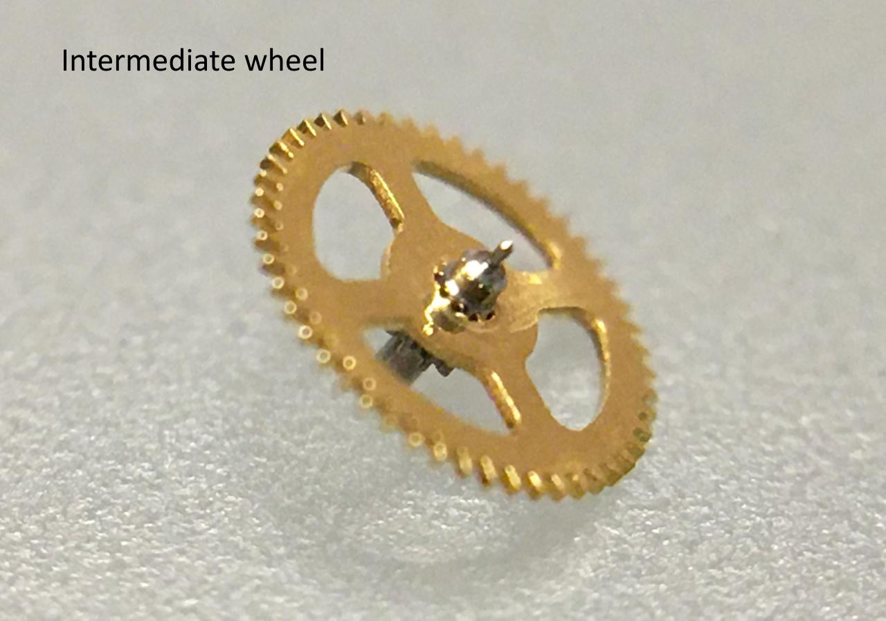
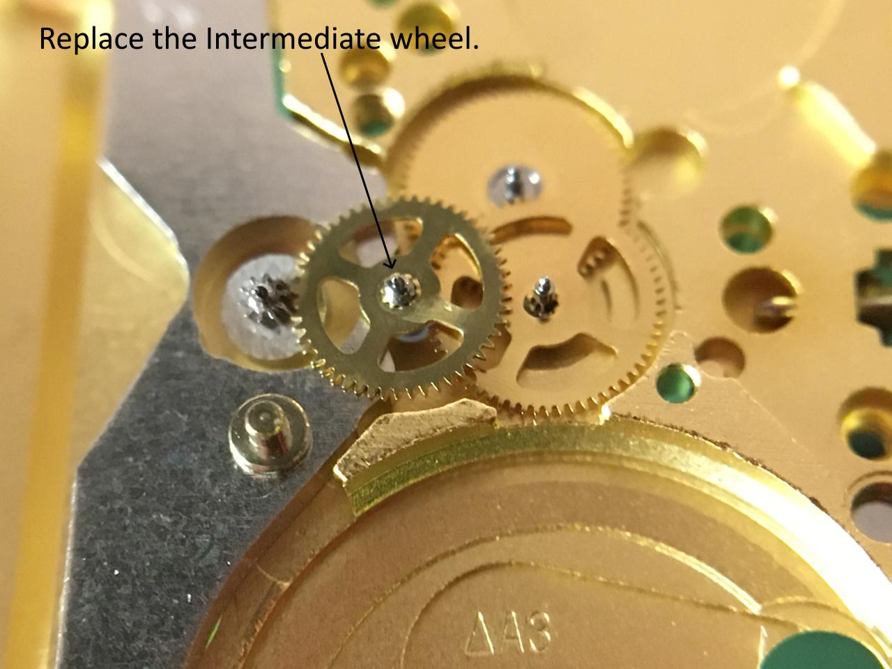
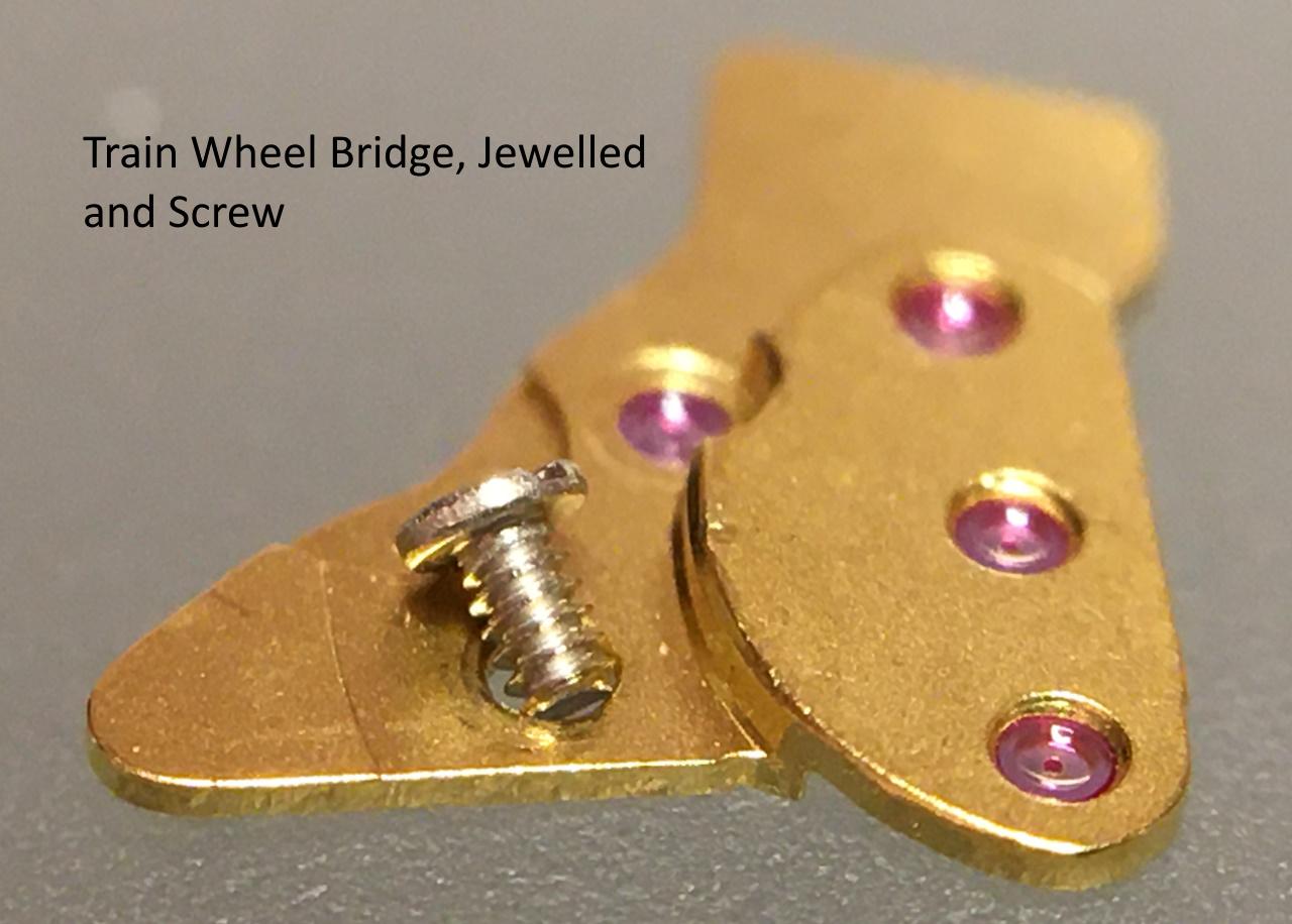
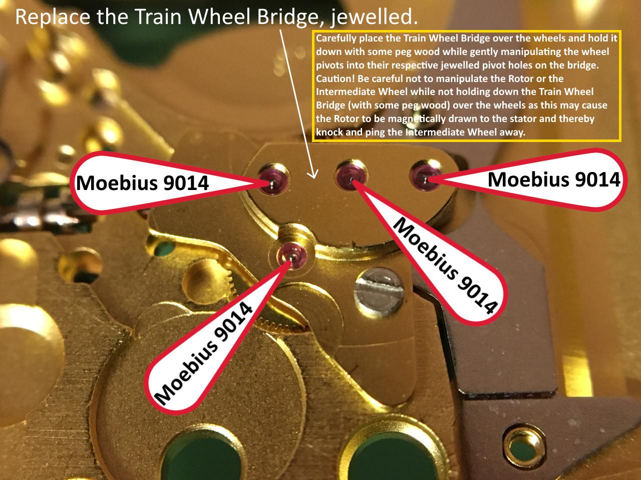
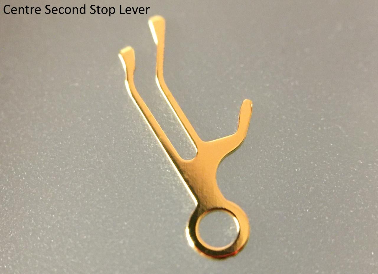
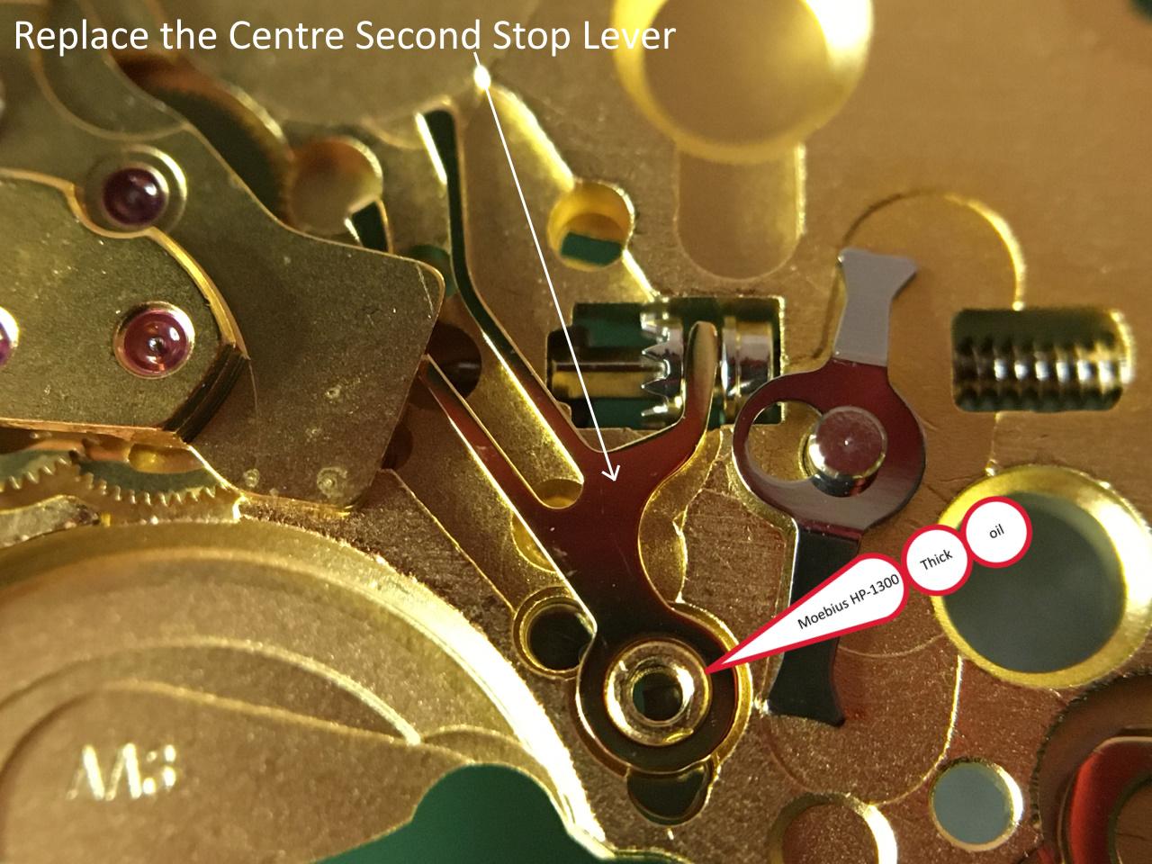
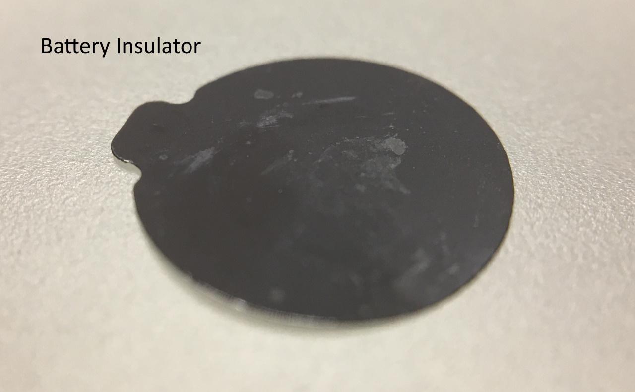
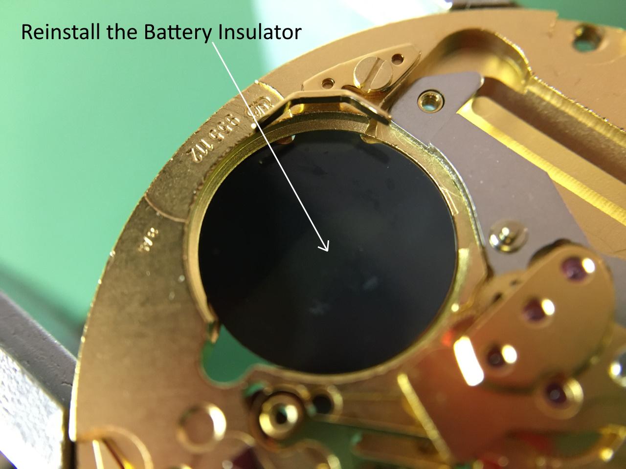
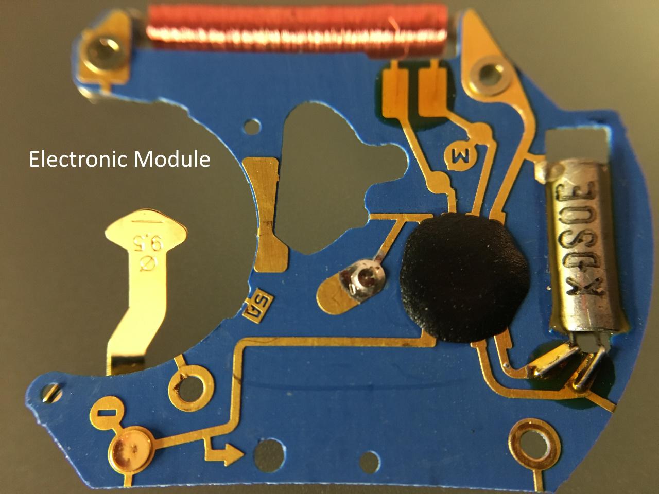
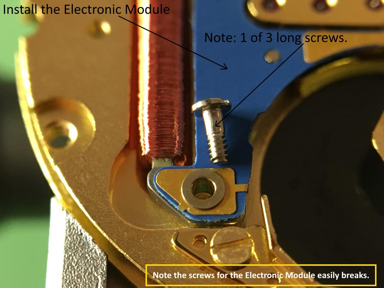
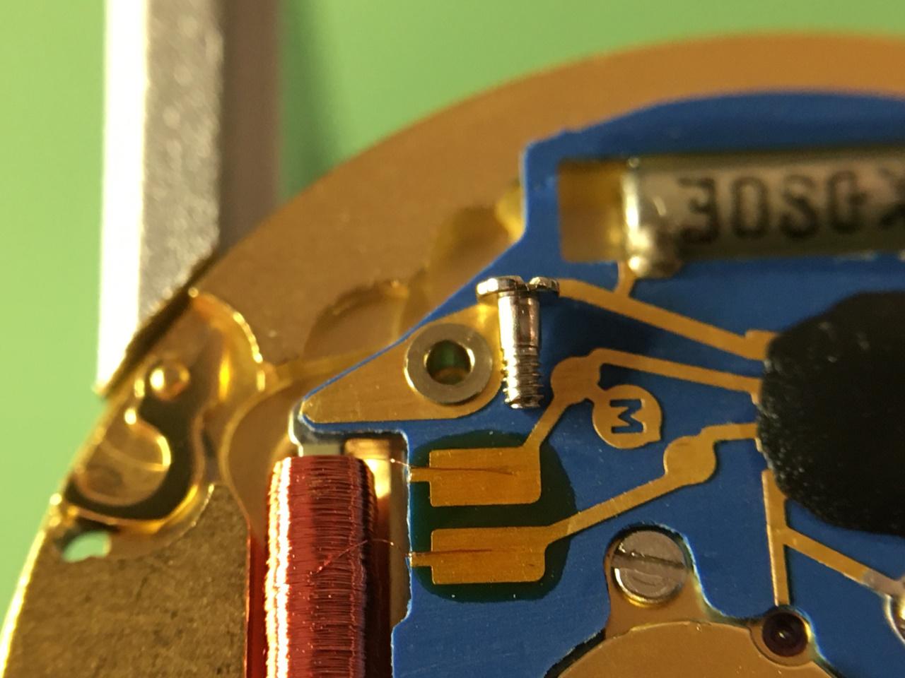
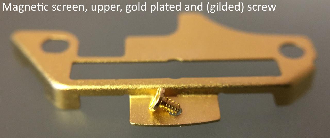
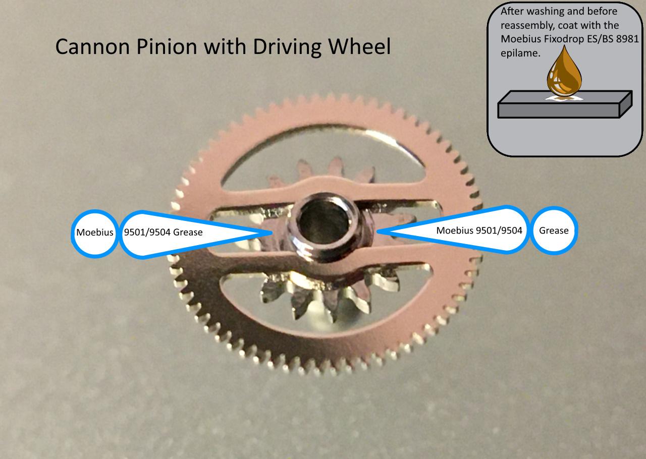
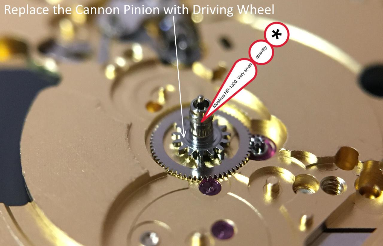
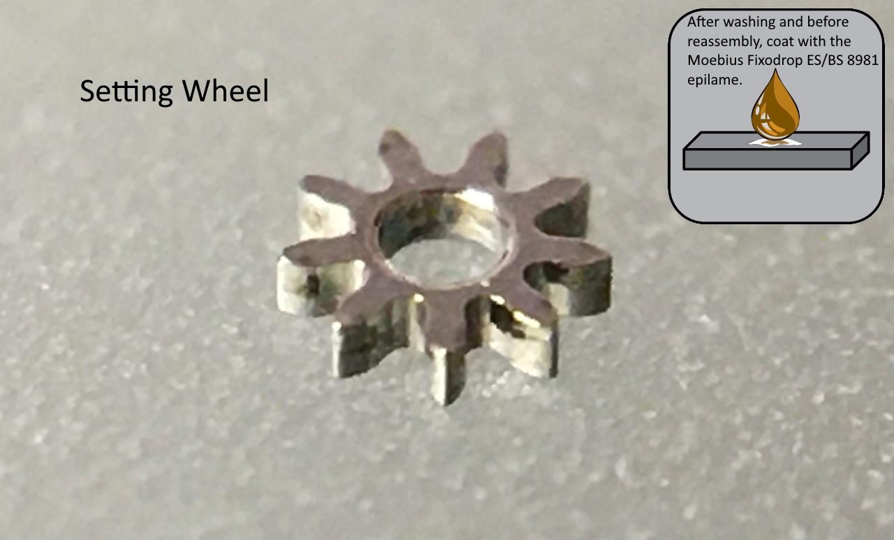
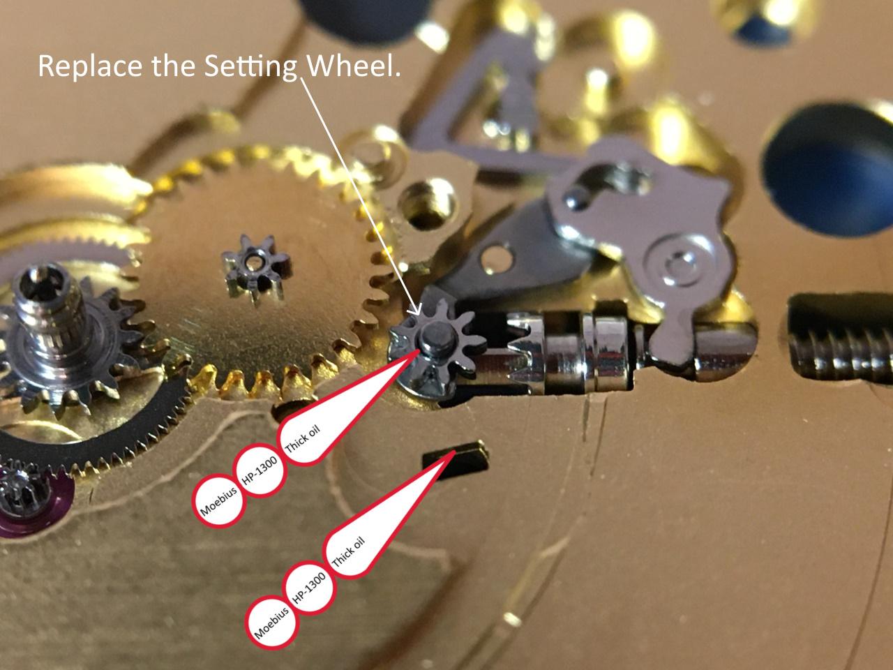
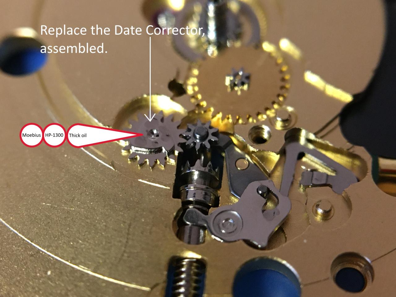
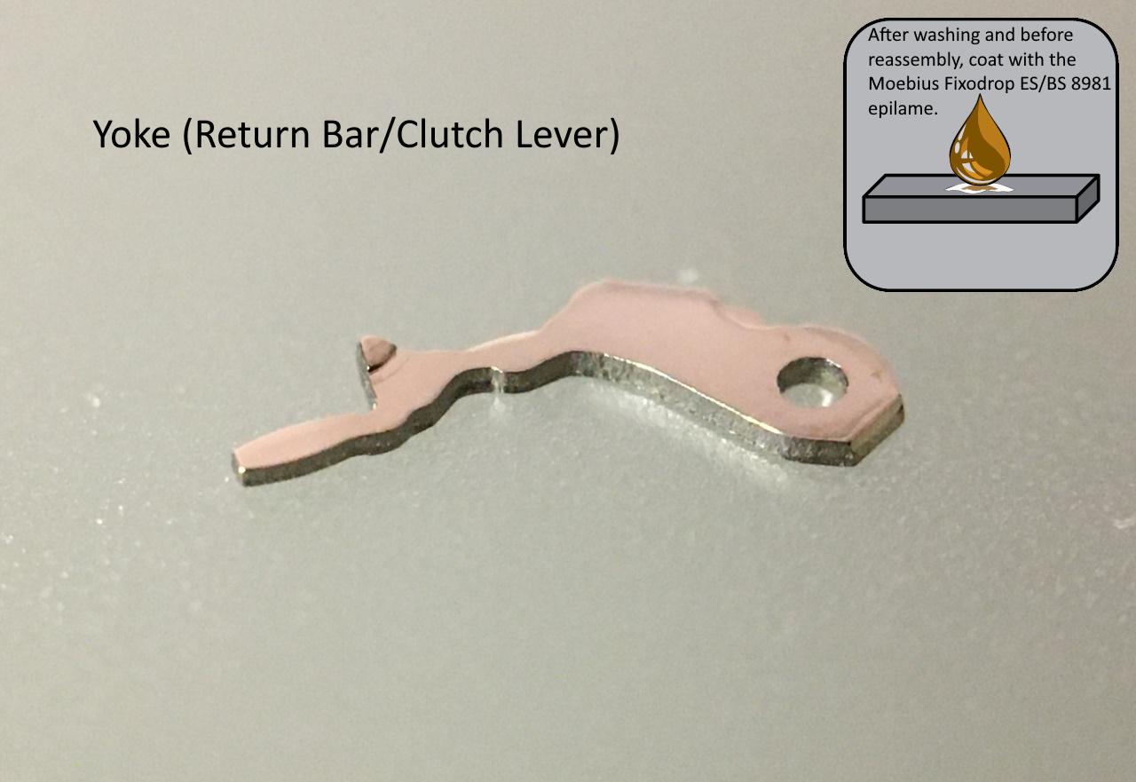
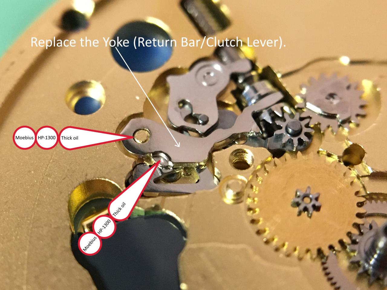
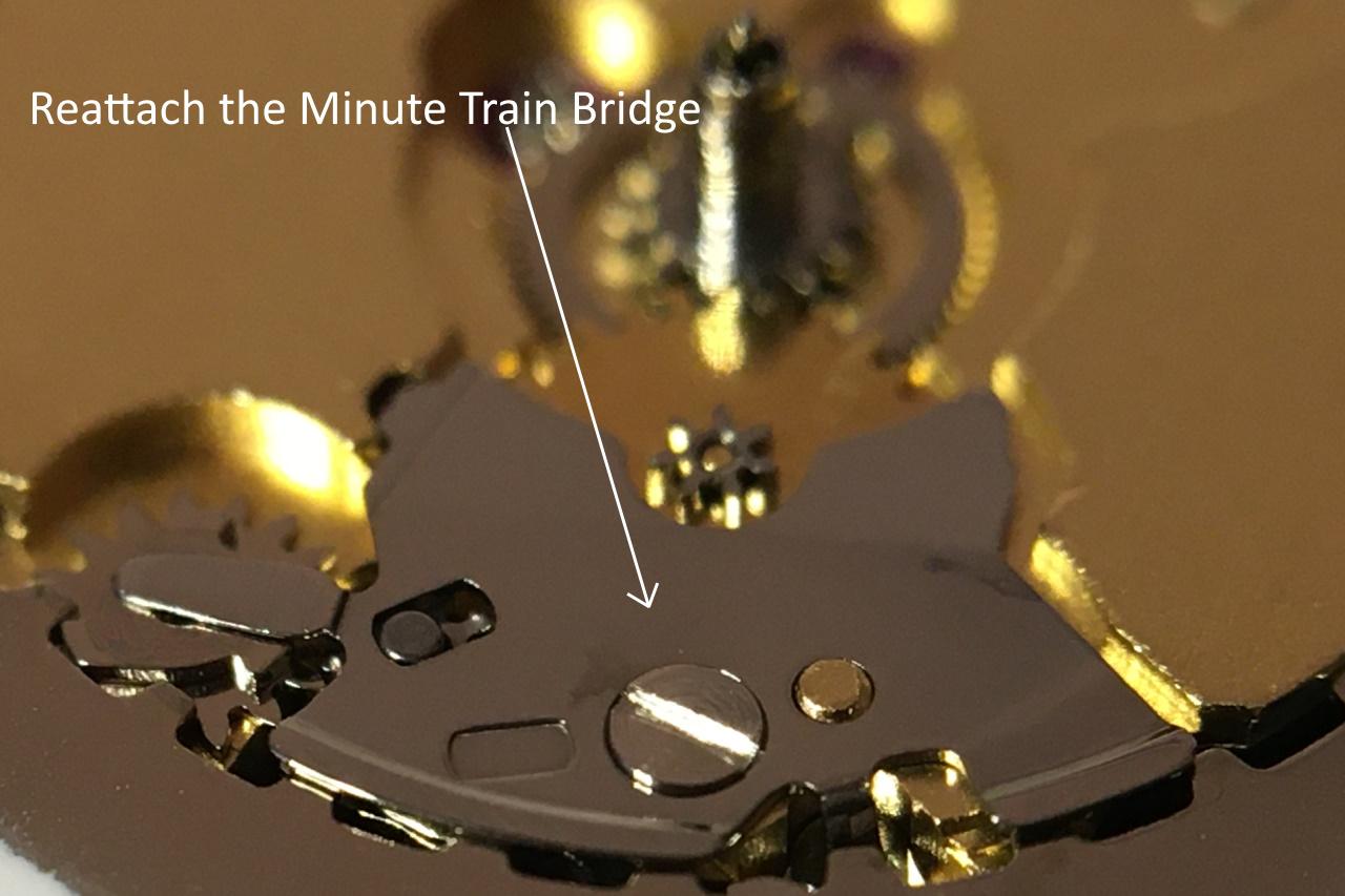
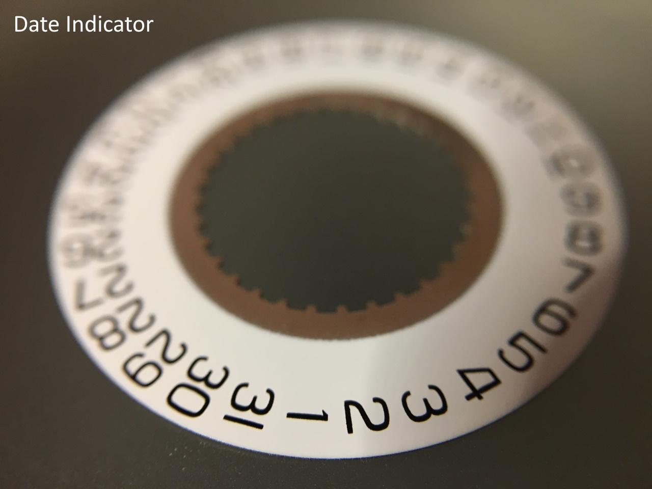
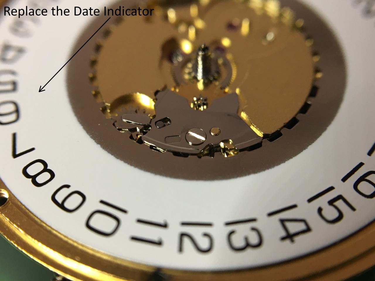
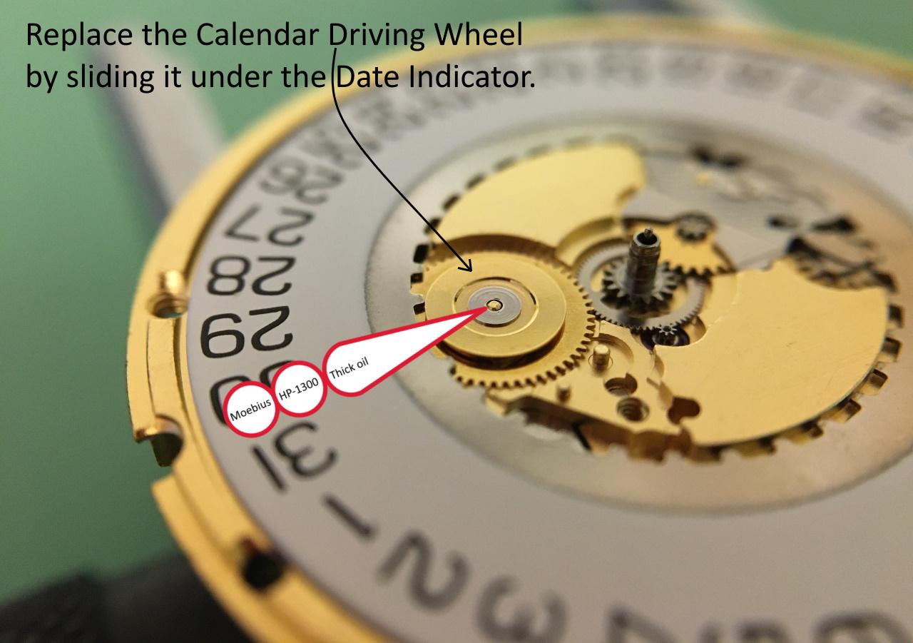
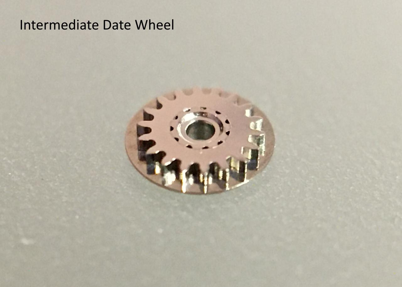
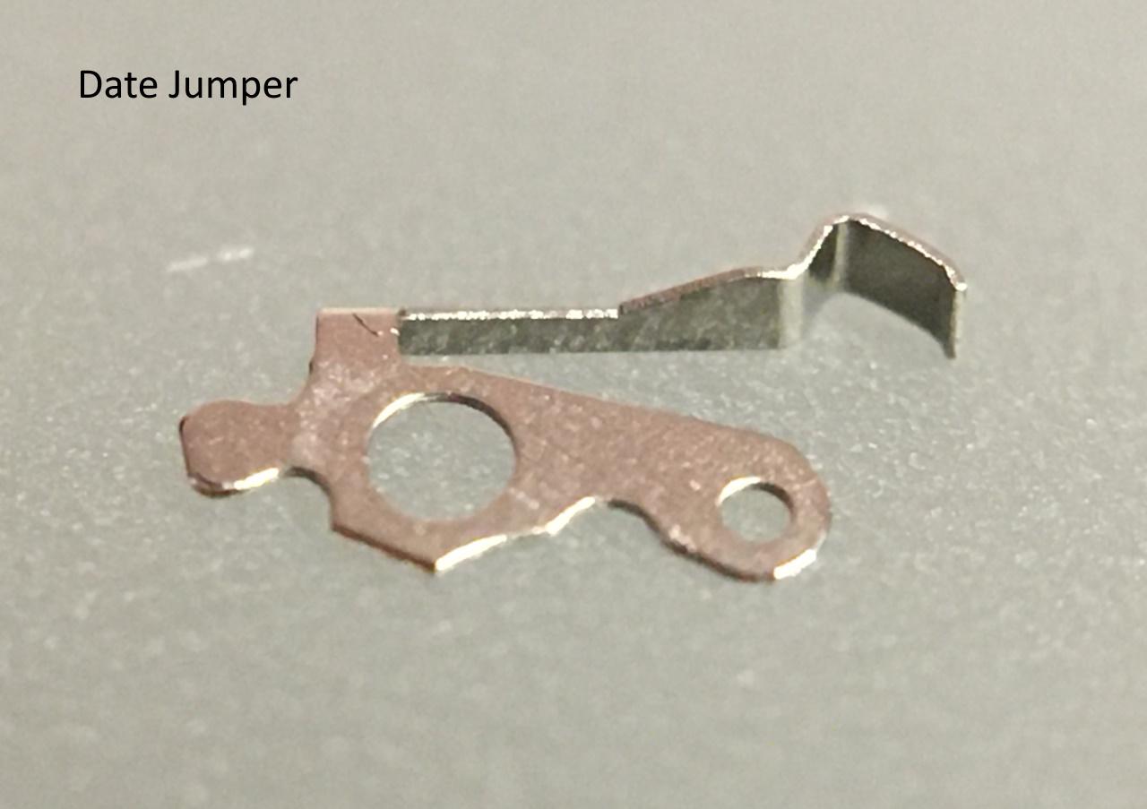
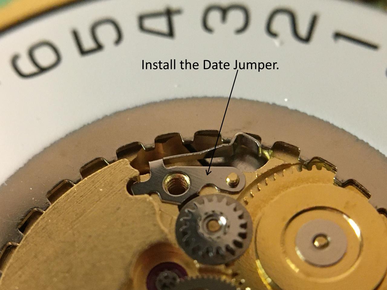
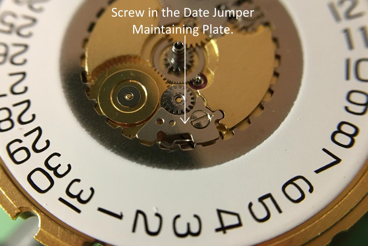
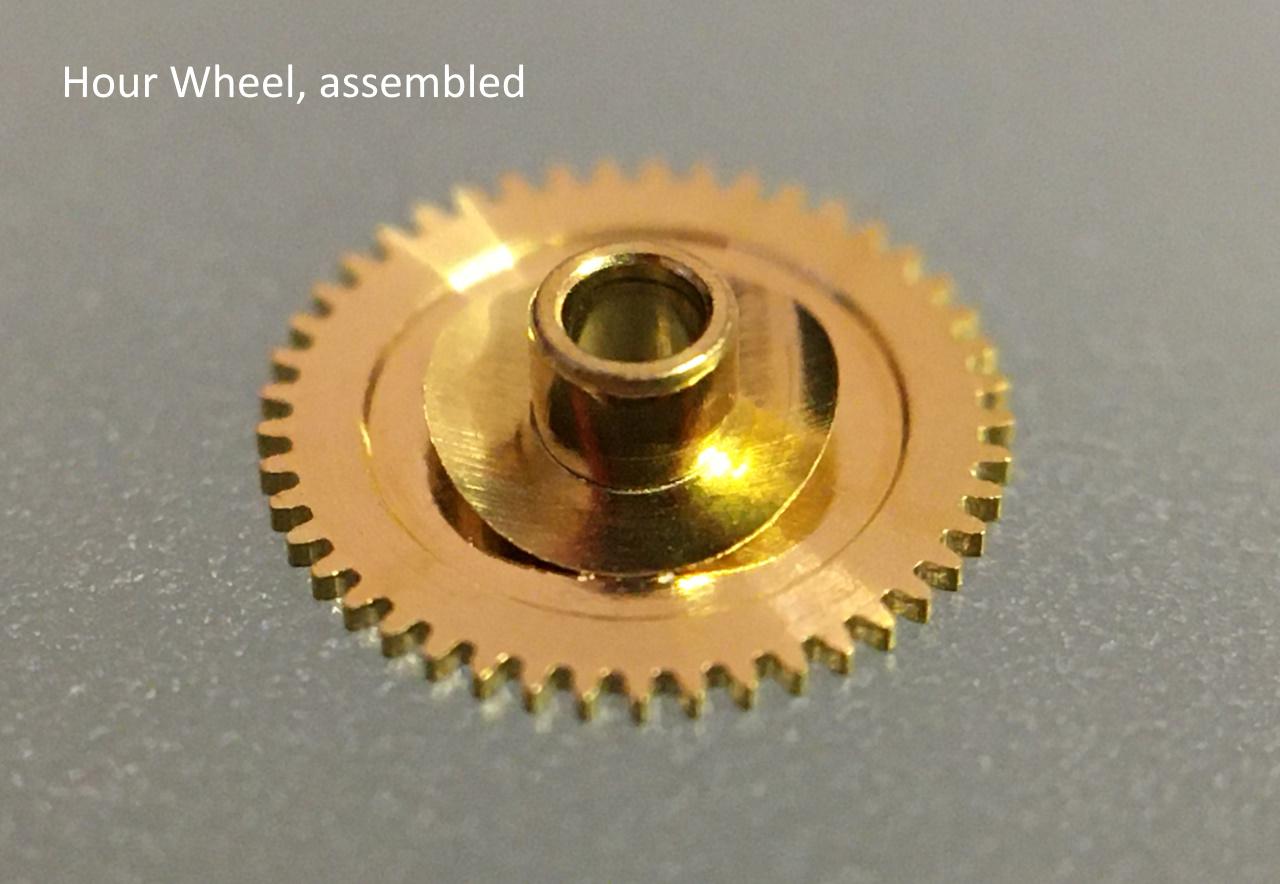
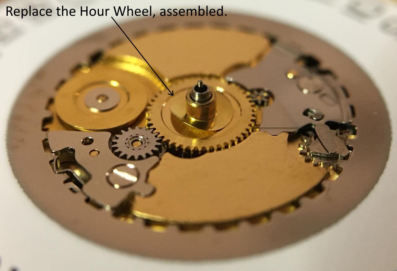
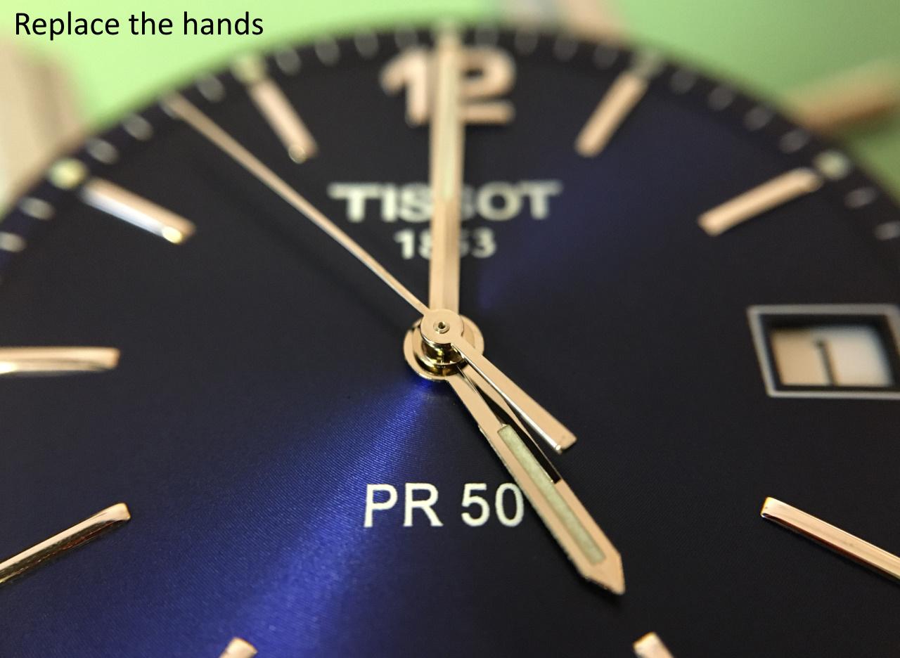
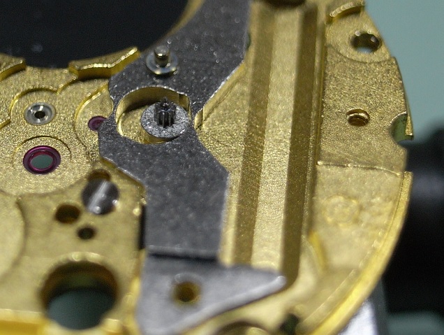
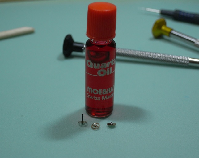
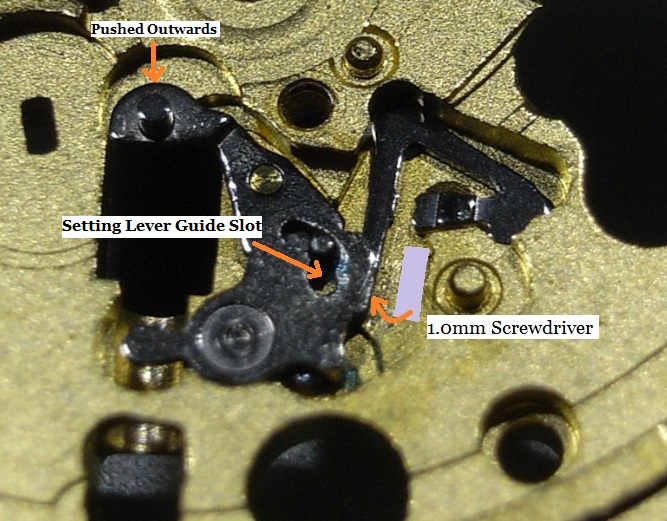
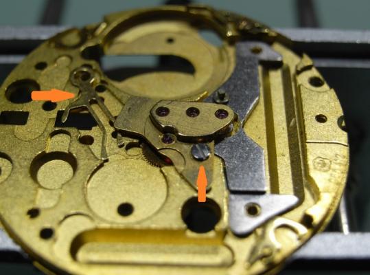
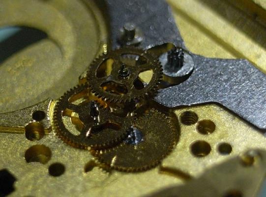
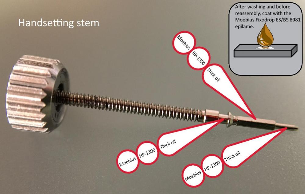
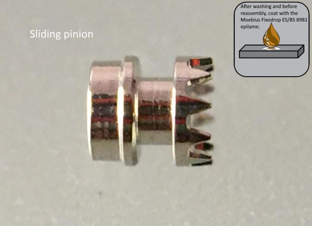
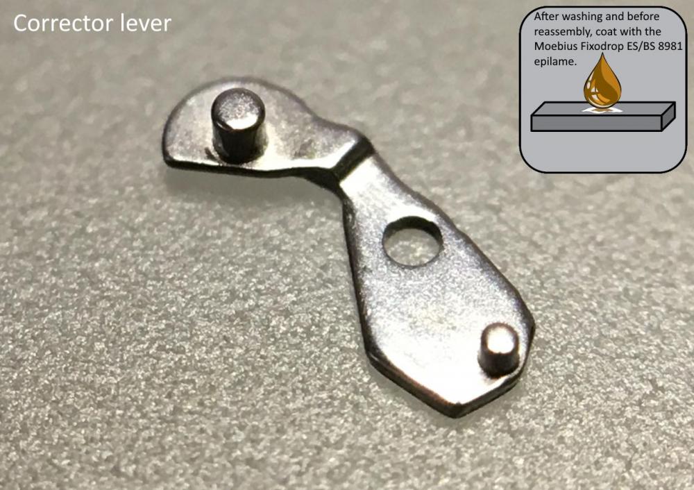
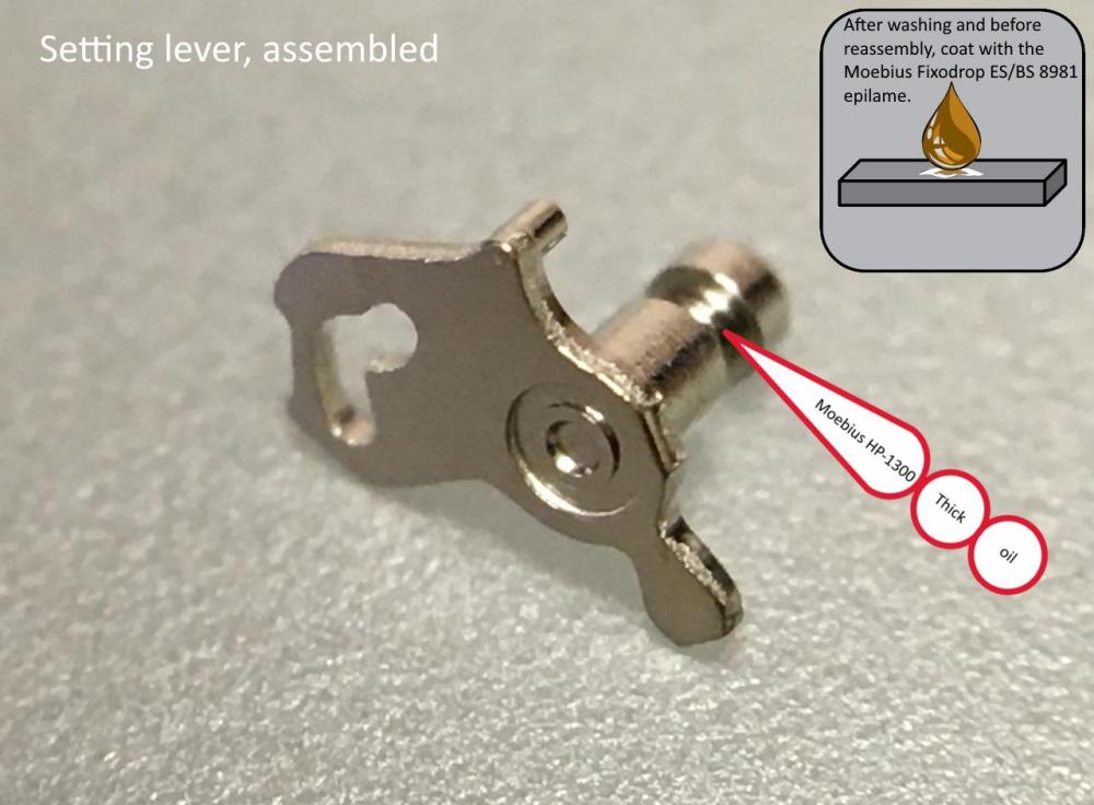
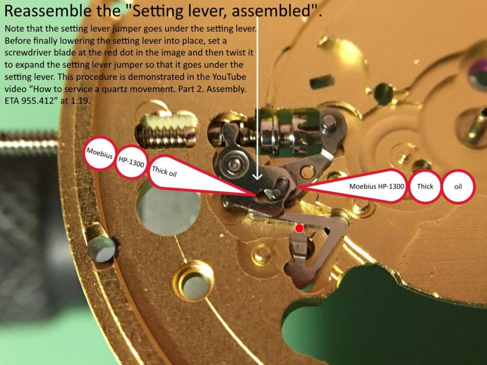
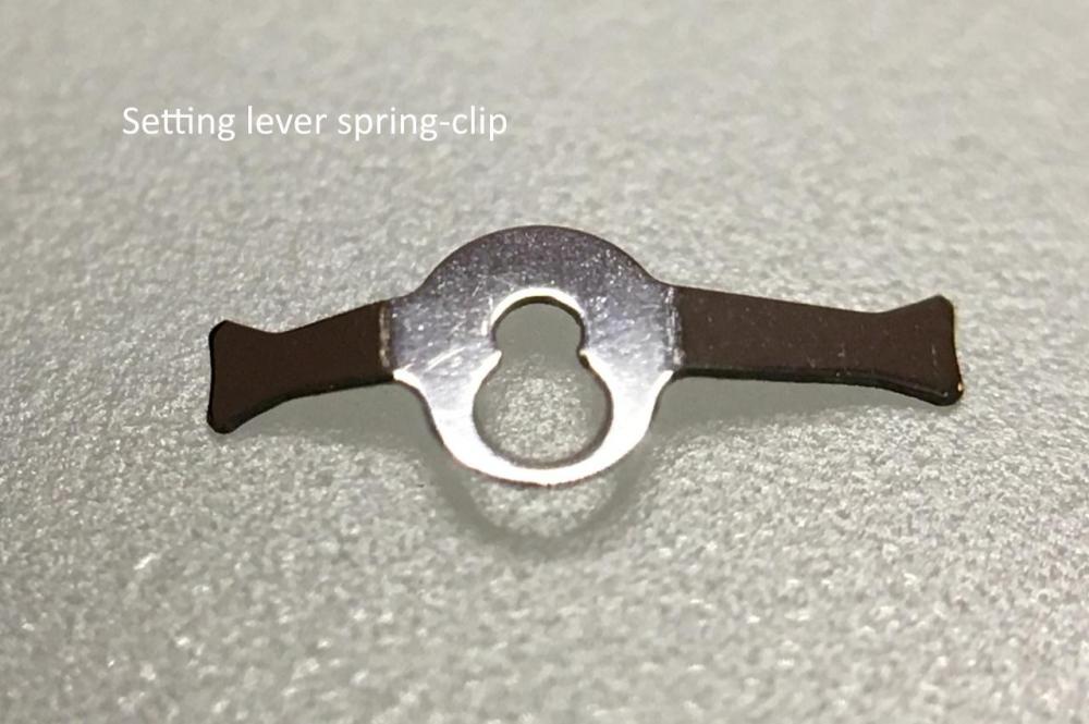
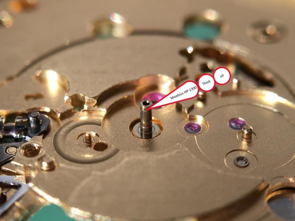
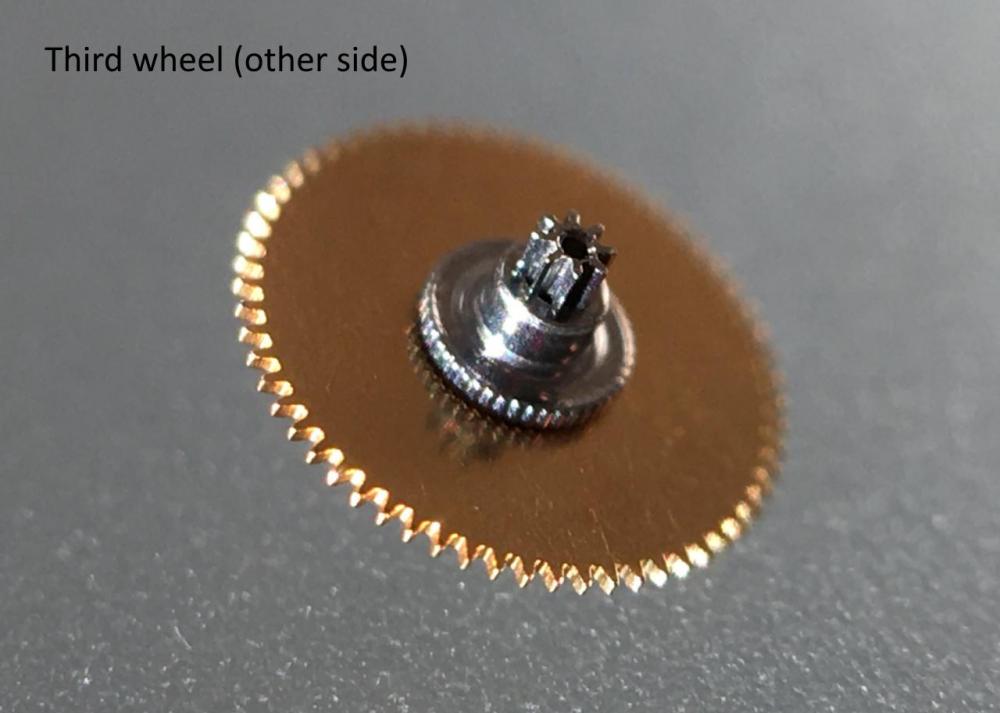
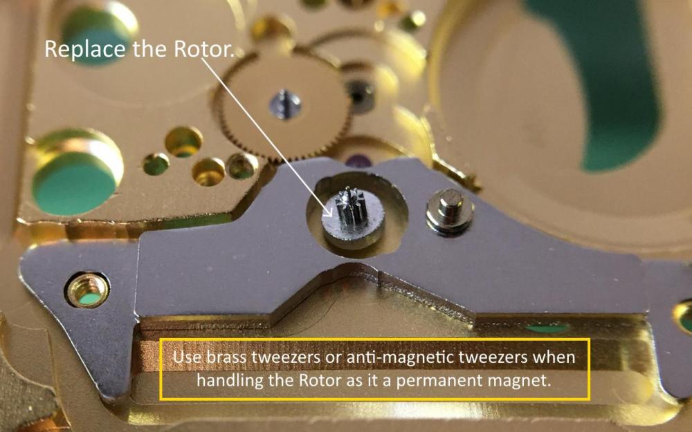
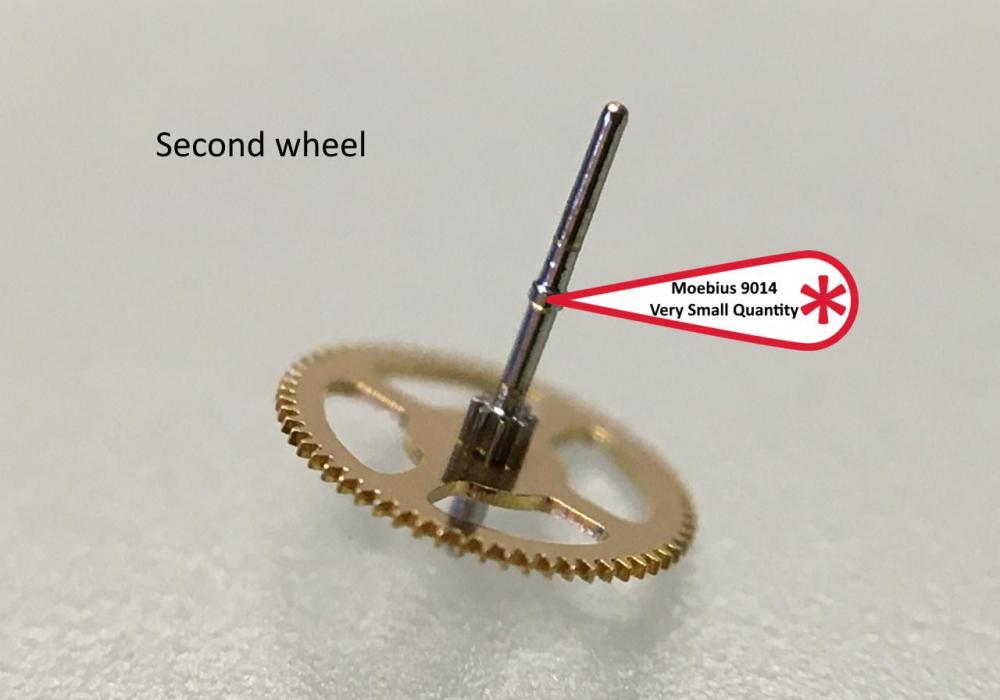
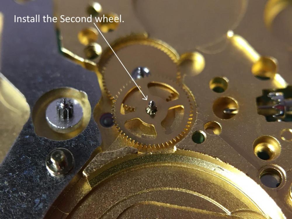
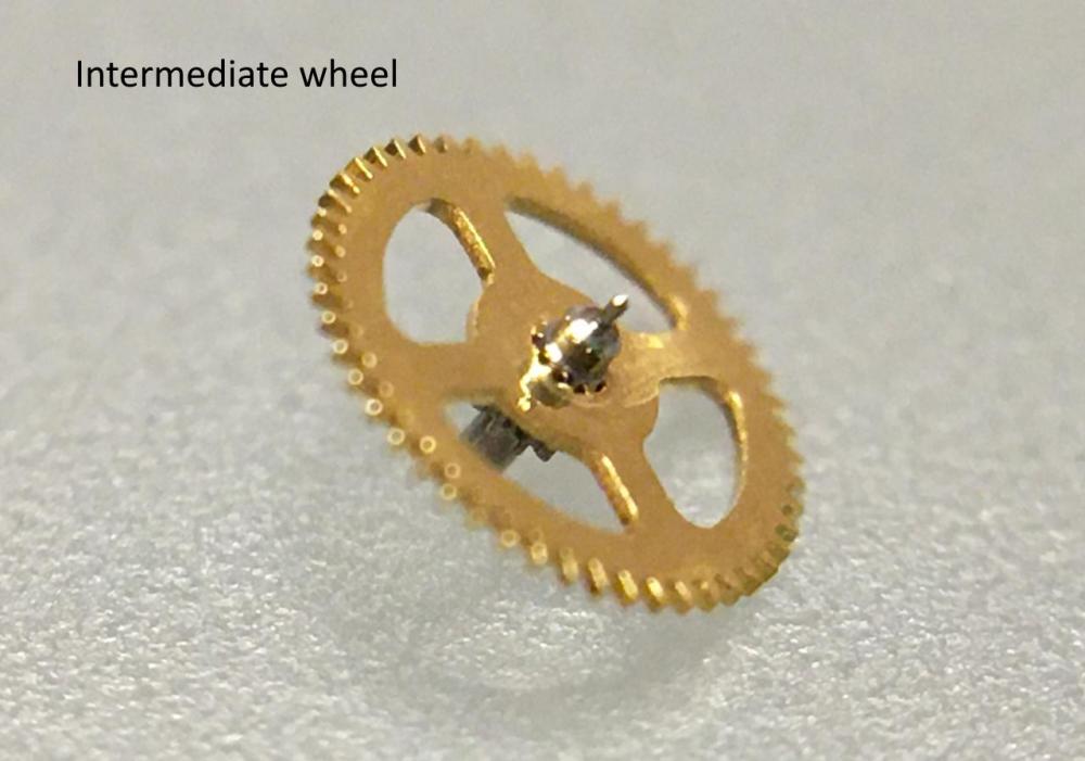
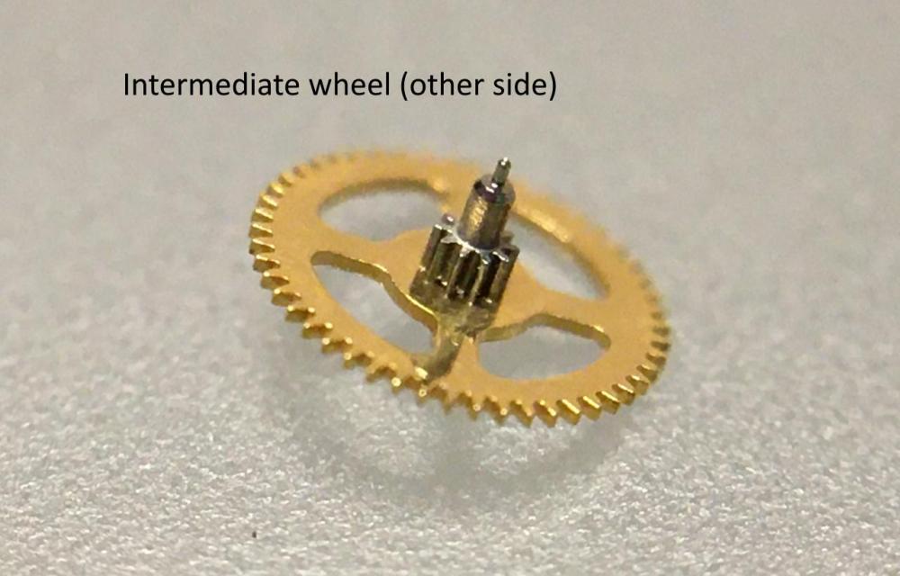
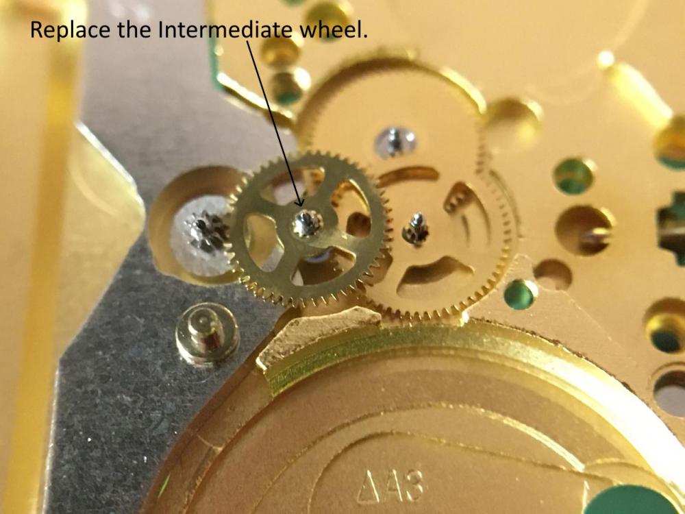
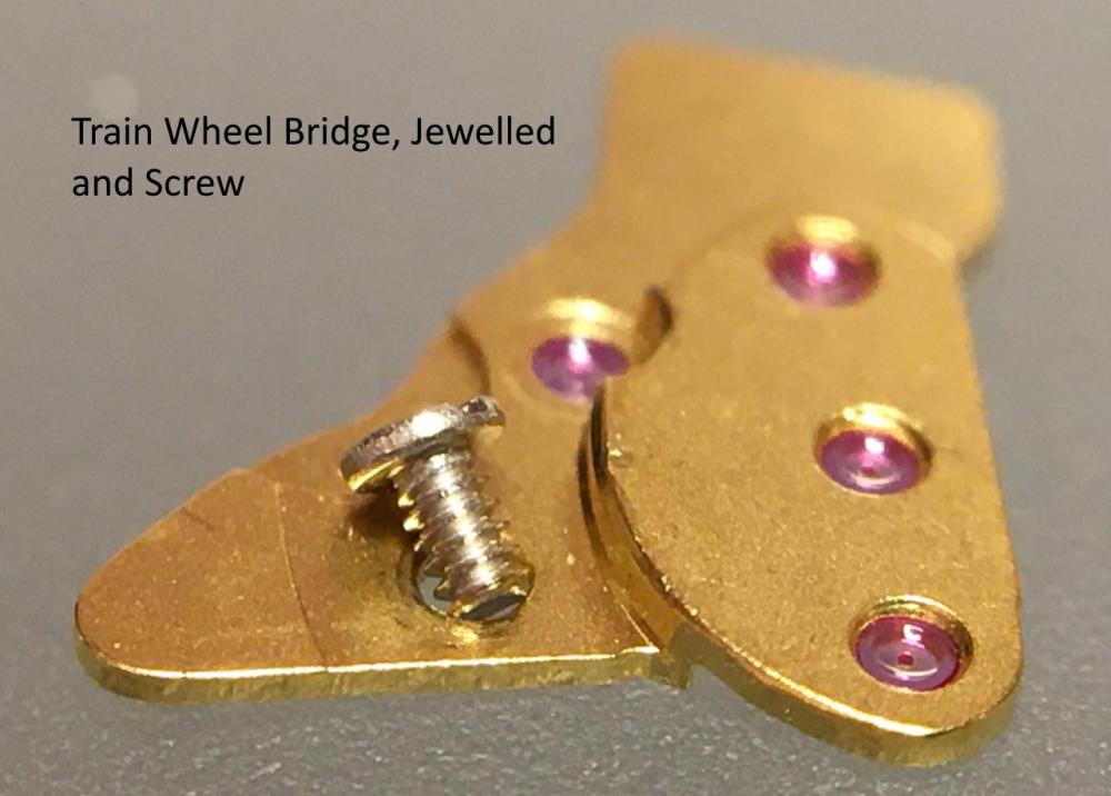
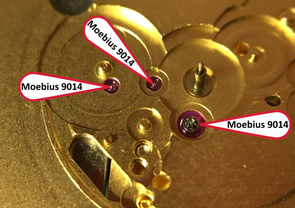
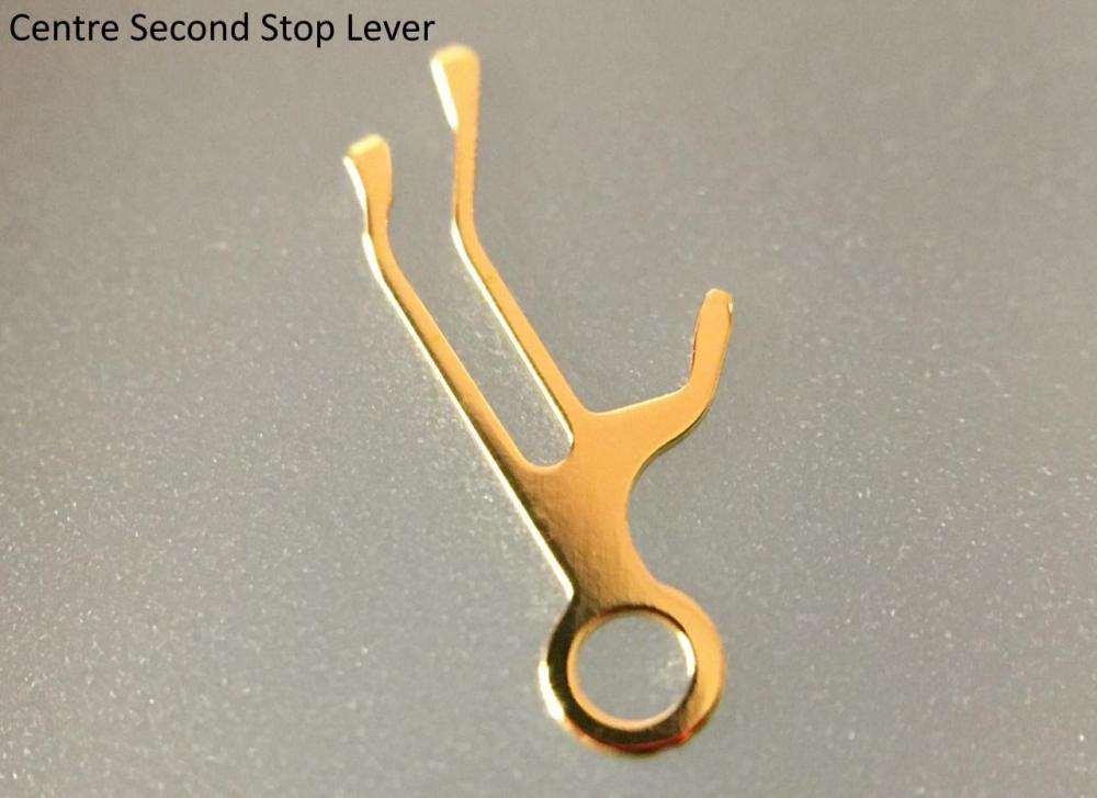
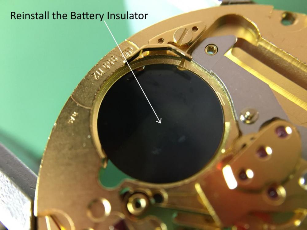
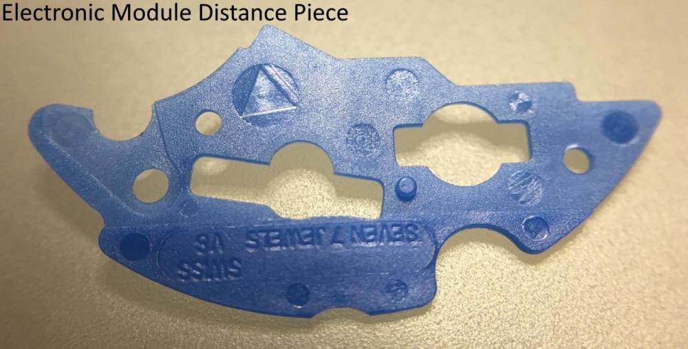
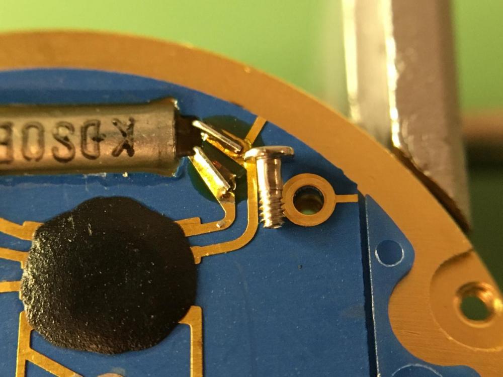
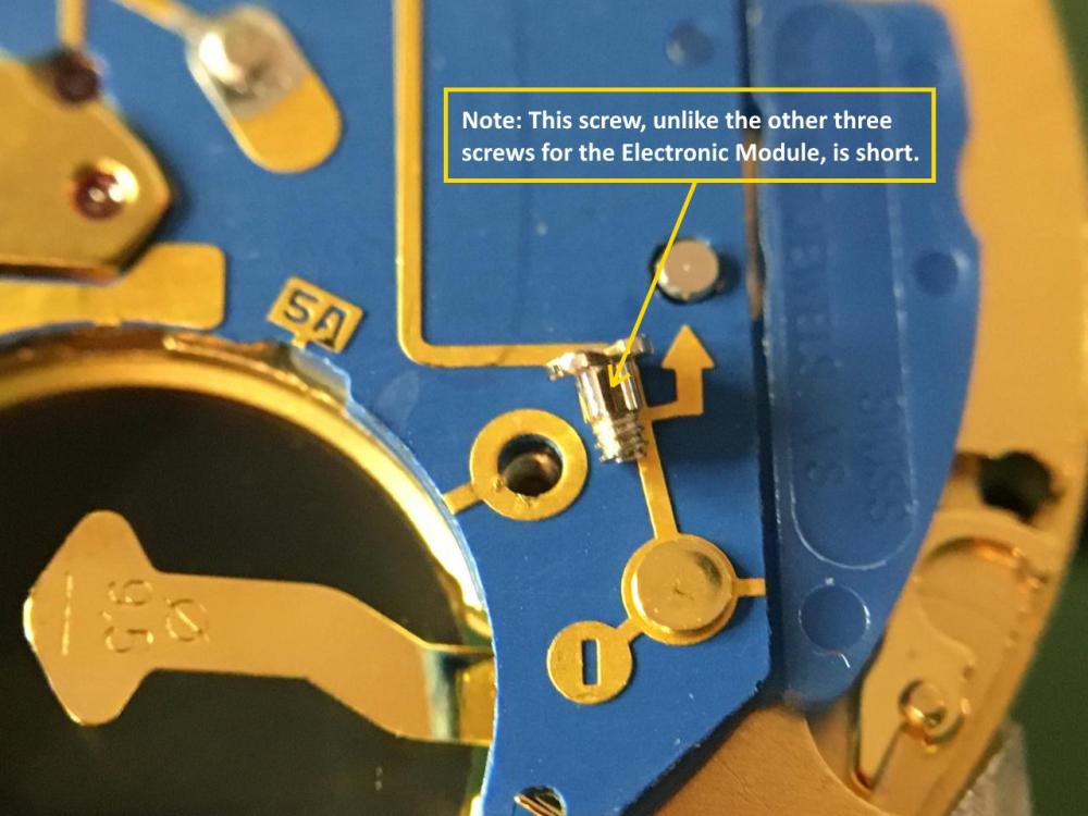
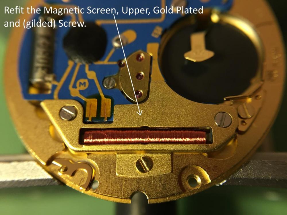
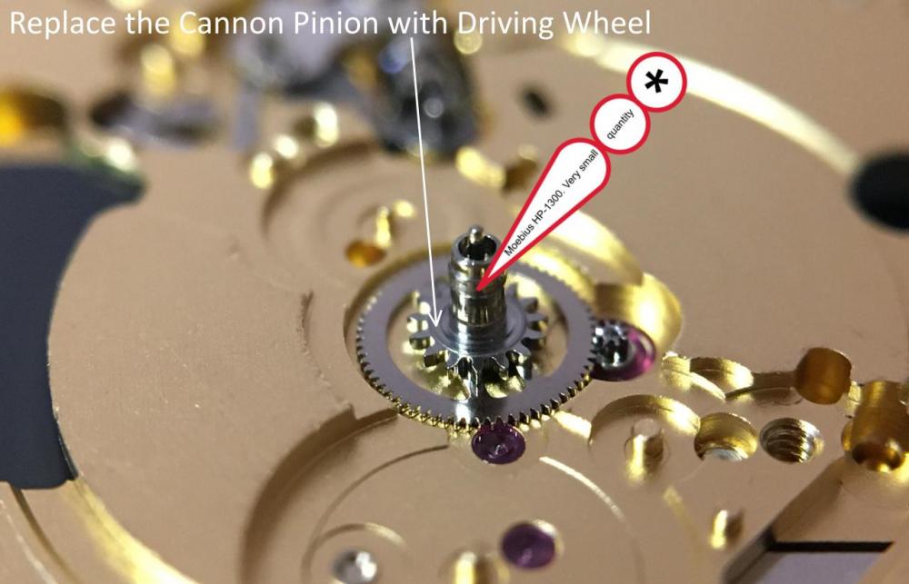
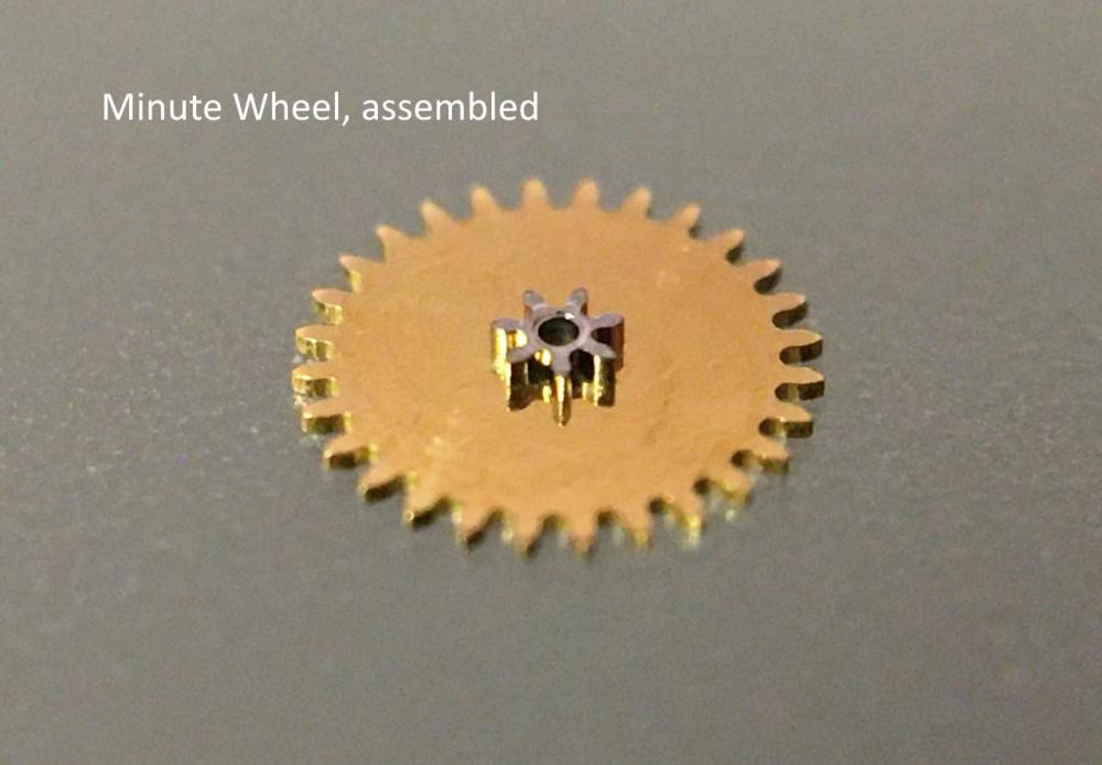
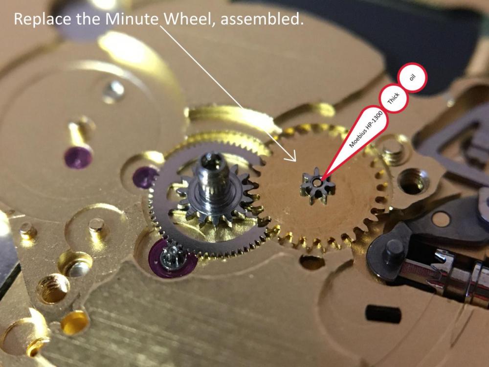
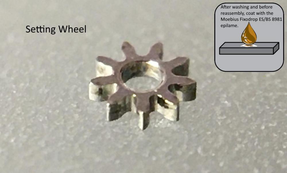
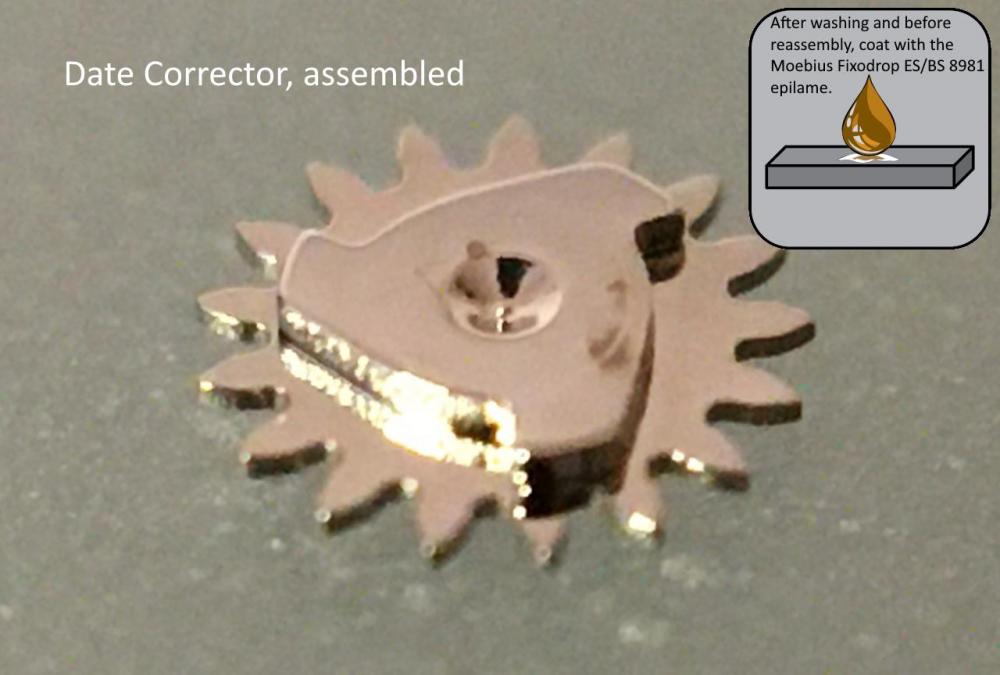
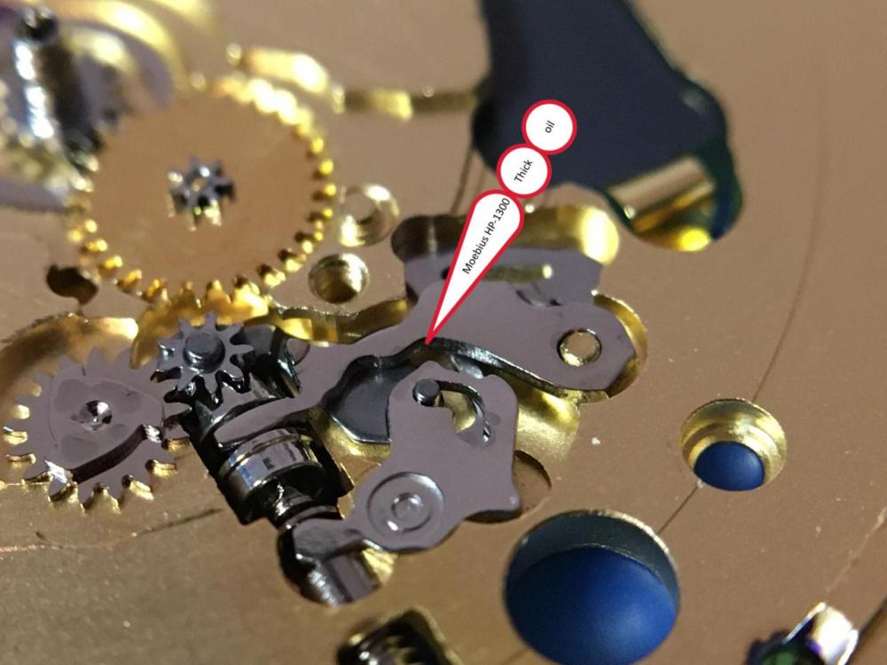
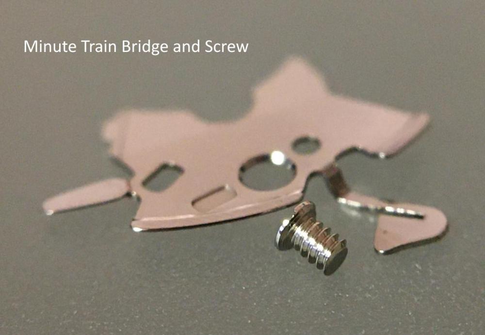
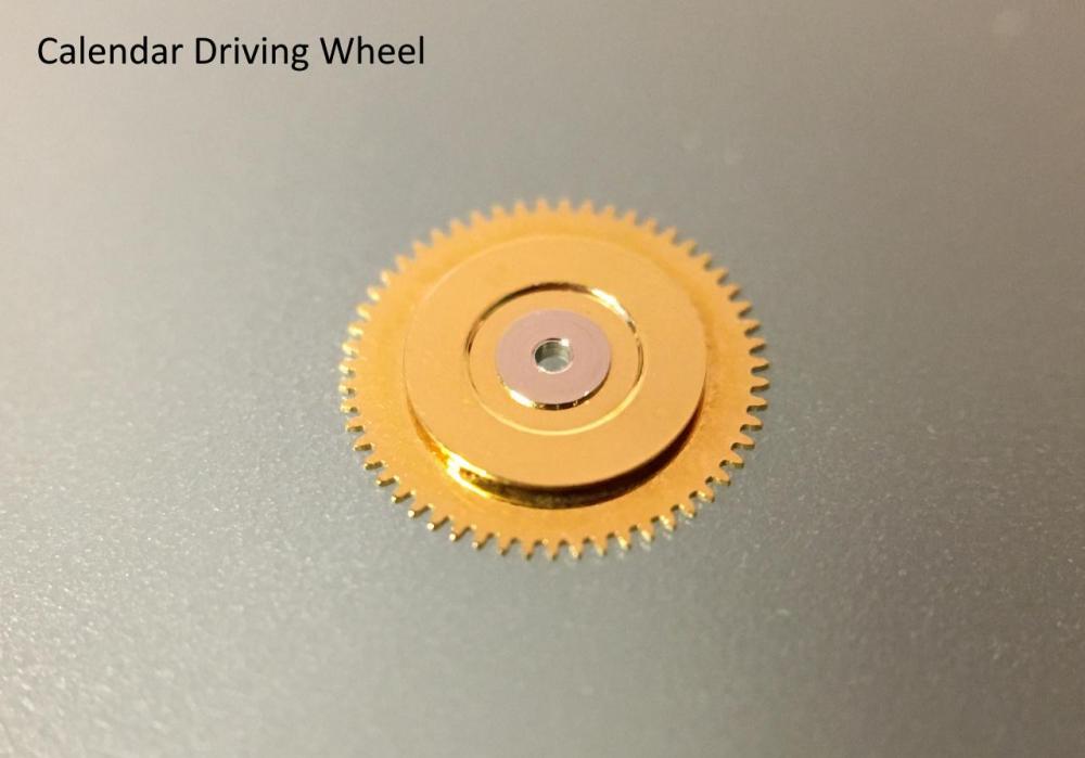
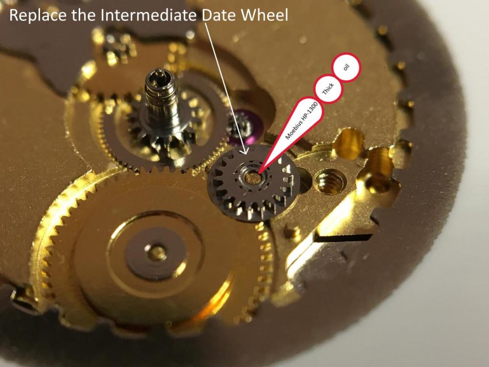
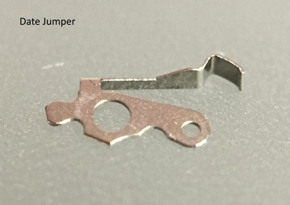
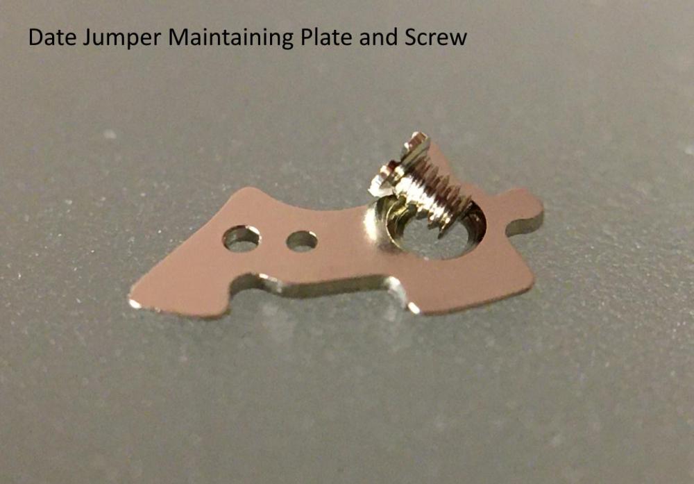
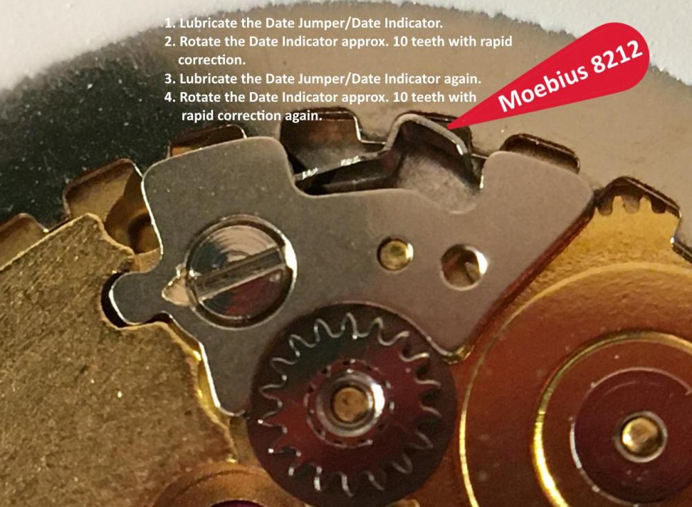
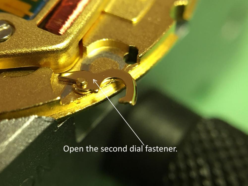
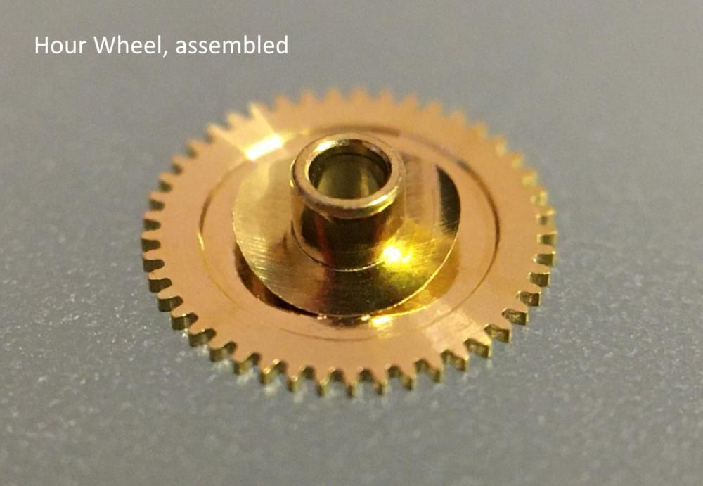
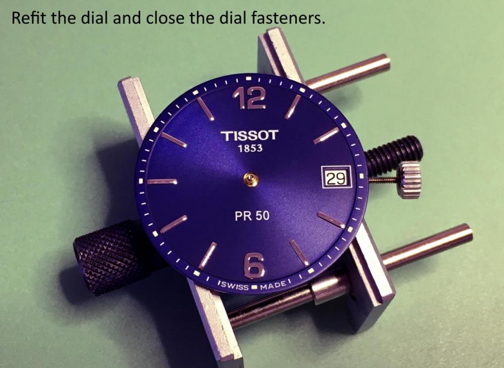
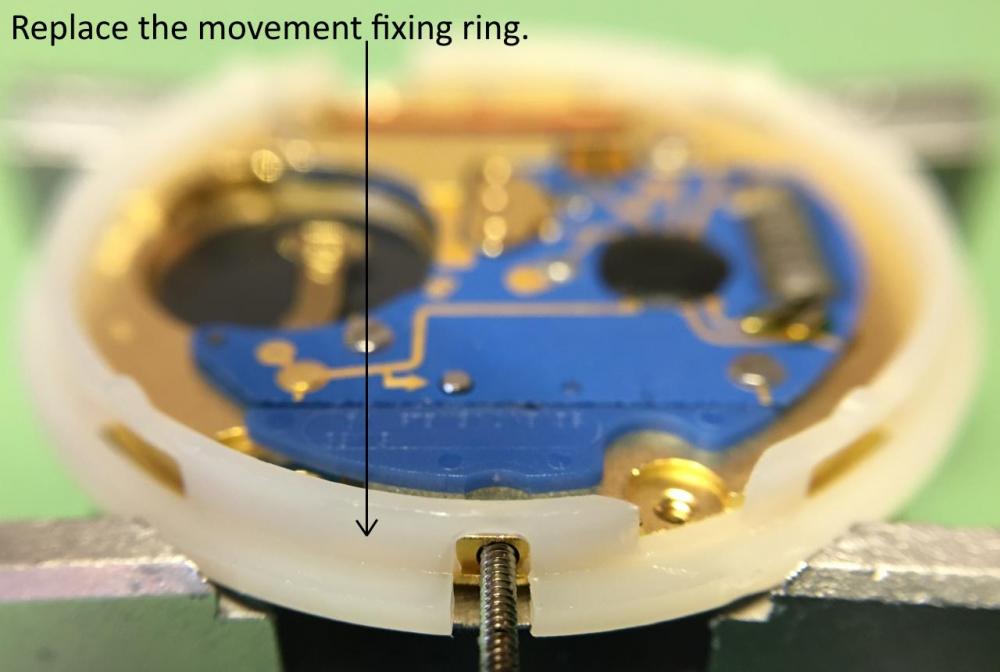
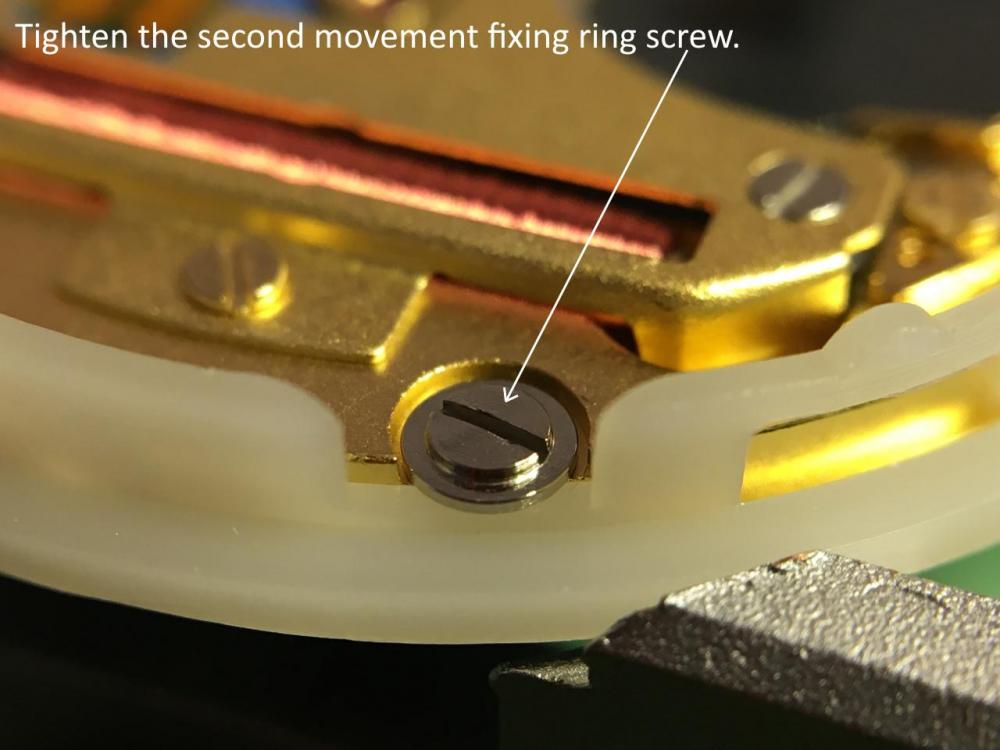
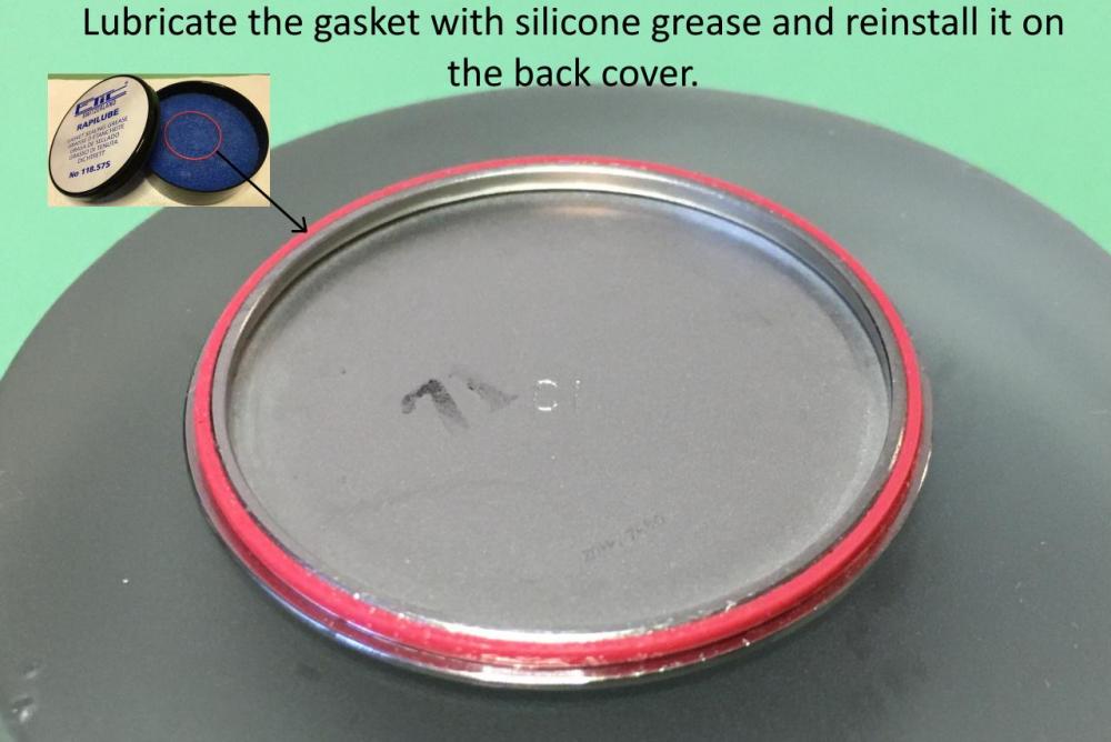
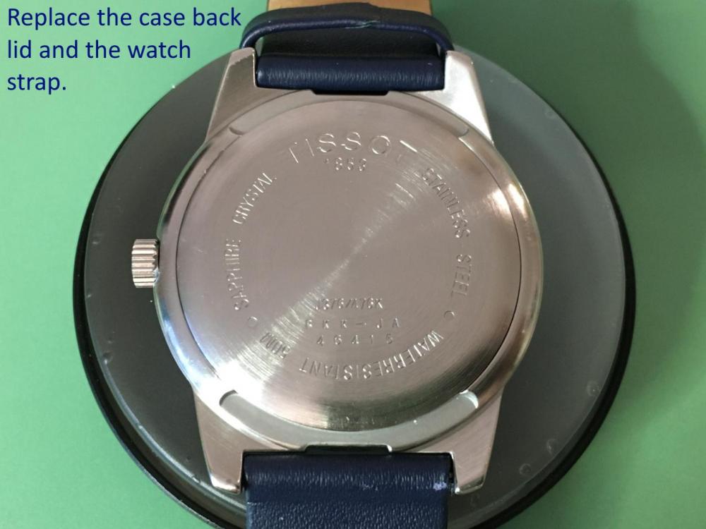
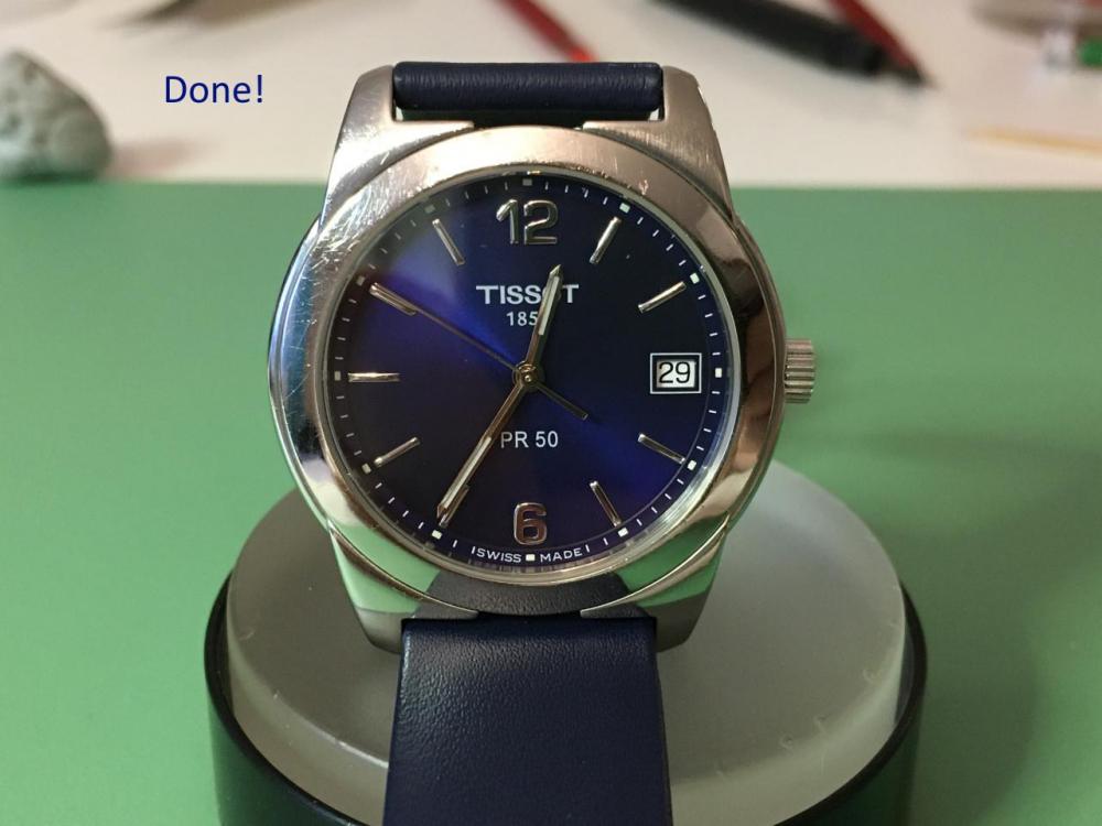
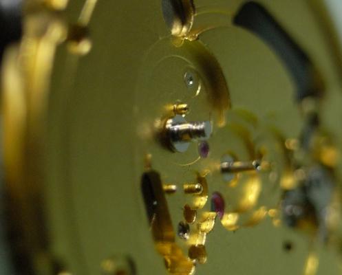
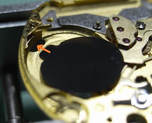
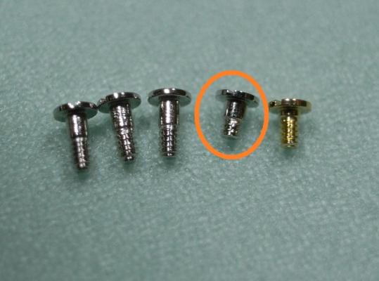
Assembly I have made the assembly walkthrough much more detailed, as putting things back together is always more tricky than pulling them apart :) Firstly install the Setting Lever Jumper and the Double Corrector Operating Lever. D5 on the Corrector Lever Pivot 9501 on the Setting Jumper To install the Setting Lever, first move the Double Corrector Operating Lever to it's most outward position, then push the Setting Lever 1/3 of the way down it's pivot, next place a 1.00mm screwdriver as shown below, and turn it clockwise. This will push the Setting Lever Jumper over to the other side of the pin on the underneath of the Setting Lever. Then push the Setting Lever home, making sure that the pin on the Double Corrector Operating Lever locates inside it's guide slot on the Setting Lever. I know this sounds a little complicated; but once you study the Keyless Work, you will understand the procedure I've explained here. Just take your time, and read through this procedure whilst looking at your work a couple of times until you are sure you've got it. Please Note: If you use a larger size of screwdriver be careful you don't push it too far over and bend the jumper ... using a 1.00mm driver is the correct size and will avoid this possibility. 9501 on the Setting Lever pivot 9501 in the guide for the Corrector Lever pin Flip the movement over and place the Setting Lever Spring Clip as shown below Then with a pair of tweezers push down on both sides of the clip and with a piece of Pegwood push it inwards so it locks in. Next install the Rotor, and you'll find due to it being magnetized, it will stick to the Stator. DO NOT try and locate it in it's jewel, as it will just pop out and stick to the Stator again, and this can be very frustrating ... but I have a little trick that will cure this :) Place one of the screws on the opposite side of the Main Plate, behind where the Rotor is located, and you'll see it will be attracted to the Rotor (as seen below). This little screw will pull the Rotor downwards and stop it being pulled over by the Stator, so you now can locate it in it's jewel. Don't forget to remove and demagnetize the screw once you've completed installing the gear train. There is a LOT of discussion on oiling quartz gear trains. The ETA Service Manual says to use Moebius 9014 on this particular movement; but I prefer Moebius Quartz Oil, as it can be used on both metal and plastic gears without concern ... why have 2 oils when 1 will suffice for both applications. Others say, don't oil the gear train at all, as it just adds load to the movement and makes it draw more current. Personally, I'd rather change a battery a little earlier than change out a worn out movement ... you choose which is cheaper. When oiling any quartz gear train, we only apply about half of what you'd use on a mechanical movement ... it's called Ghost Oiling. That being said, ghost oil the jewel for the Third Wheel with Quartz Oil as shown below. Ghost Oil the upper part of the Second Wheel with Quartz Oil as shown below Fit the Gear Train into the Main Plate. Place the Gear Train Bridge over the wheels, locate the pivots carefully until all are freely spinning, and tighten down the bridge. Remember once the screw makes contact with the bridge, STOP, and recheck the free spinning of the train before completely tightening the screw. Once the Bridge is secure, place the Stop Lever and Switch back onto it's pivot. D5 for Stop Lever and Switch pivot Quartz Oil for all Gear Train pivots (remember to oil both sides) Next install the Battery Isolator, making sure to push the tab into it's slot as shown below. Then install the Isolator Block Next we need to short out the screws for the IC Board. You'll see there is a Gold Screw, this is for the Coil Protector, and then there are three screws of the same length, and one shorter one. The shorter screw must be place into it's correct hole. Locate the IC Board onto the movement. Before I screw the IC Board down, I always fit the Coil Protector first. This helps avoid any damage if you accidently slip off a screw head. Remember to use the Gold Screw. Next place all the rest of the screws into their holes, noting the position where the short screw is to be located. This side of the movement is now complete. Time to flip it over and complete the Keyless Work, Motion Work and Calendar Work. Place the Sliding Pinion into it's position. Please Note this is a spare movement I'm using here, and I don't have a stem. If you have a stem, now is the time to install it. 9501 in the grove for the yoke on the Sliding Pinion 9501 on the stem Place the Yoke into position D5 on Yoke Pivot Install the Setting Wheel and Date Corrector D5 on Setting Wheel pivot D5 on Date Corrector slot Next is lubricating the Cannon Pinion. This is one step that MUST be done correctly, otherwise too much friction will occur and you'll damage the Setting Wheel in short order. 9501 Canon Pinion fiction points Place the Canon Pinion and then the Minute Wheel D5 Minute Wheel pivot D5 Ghost Oil the Canon Pinion Tube Attach the Motion Work Bridge and secure it down. Place the Date Ring onto the movement, and then slide the Date Indicator Driving Wheel into place, so the teeth of the Date Wheel are inside the Driving Wheel. Then install the Intermediate Date Wheel. D5 Date Indicator Driving Wheel pivot D5 Intermediate Date Wheel pivot Lubricate the foot of the Date Jumper Spring as shown below 9501 Date Jumper Spring foot Place the Date Jumper Spring into position on the movement Place the Date Jumper Maintaining Plate and secure it. Check the date and time setting, making sure the quick date works smoothly. Check the feel of the Motion Work, making sure there is not too much or too little friction from the Canon Pinion. Your movement is now completely serviced, all that's left to do is fit Hour Wheel, Dial and Hands :woohoo-jumping-smiley-emoticon: It's good for another 100,000 miles or 5 years ... whichever comes first ^_^ I hope this walkthrough both helps and encourages you with servicing your 955/6 ETA Movement


 1 point