Leaderboard


Popular Content
Showing content with the highest reputation on 03/11/19 in all areas
-
To calculate the train, you can start from the center wheel for beats per hour or in your case the 4th wheel for beats per minute (if the watch has a 4th wheel that turns once per minute, usually but not always the case- of course it is for a chrono), as you like. From center wheel you multiply all the wheels, CW x 3rd x 4th x escape, x 2 (for the two beats for a tooth to "escape"), and divide that by the driven pinions multiplied together, so 3rd x 4th x escape. That gives the beats per hour. In your case it's from the 4th, so 84 x 20 x 2= 3360 divided by 7=480 that's the beats per minute, or 8 per second, or 28,800 per hour.2 points
-
You calculated 24 revolutions of the escape wheel per minute which is the error in my point of view. Looking at a working escapement you will find that it needs 2 beats to let the escape wheels move 1 tooth further. So the ew makes 12 revs per minute and your further calculation fits.2 points
-
I've watched again (and again) the lesson from Part 2, section on stripping the movement, video on Removing the Balance. I noticed that Mark, having taken the balance out of the movement put it on his workbench where it was supported by its lower pivot! He next lifted it and put it down properly flipped on its cock. Is this the recommended way to do it? Isn't it dangerous to put balance wheel, with all the weight of the cock, down on the (lower) pivot? Am I worried too much?1 point
-
I havn,t seen the video. What breaks a pivot is impact ( a shock). Not only the weight of a cock, not even the weight of the whole movement or the whole watch, would not damage a pivot if gently place on pivot. It is like trying to drive a nail into wood by pushing on it as hard as you can, wont do any good. While hitting on it's head with a hammer would drive the nail in. Push is force , hitting with hammer is impact ( shock) . This is a subject of basic dynamic. Regards1 point
-
Great stuff! Glad to be of help1 point
-
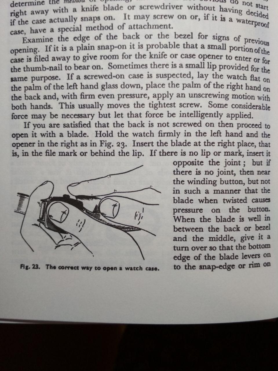
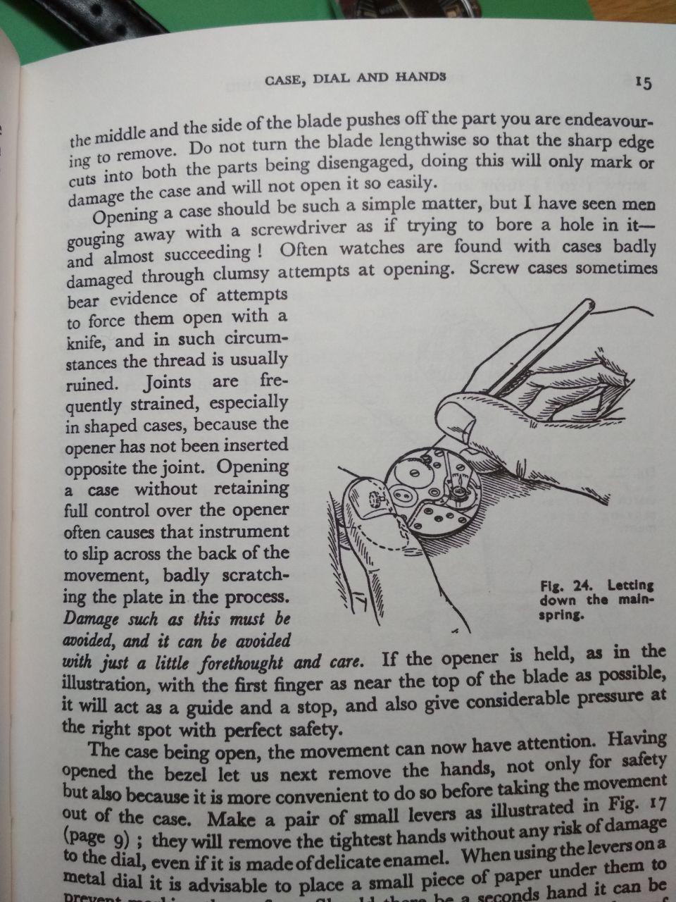
Great stuff, that looks like the notch to me! Definitely no tool marks on it though. The technique for removing is described in Donald LeCarle's book here, but maybe someone here has some tips on removing the bezel more carefully (I, for one would loose sleep over putting a mark on that solid gold case)
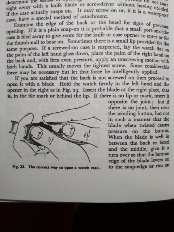
 1 point
 -
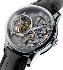
It looks little like a Wuilleumier Freres self winding pocket watch movement.... A fine piece. https://watch-wiki.org/index.php?title=Datei:Wuilleumier_Freres,_Swiss,_Geh._Nr._7622,_circa_1890_(1).jpg1 point
-
Hello, you will find all information in this thread:1 point
-
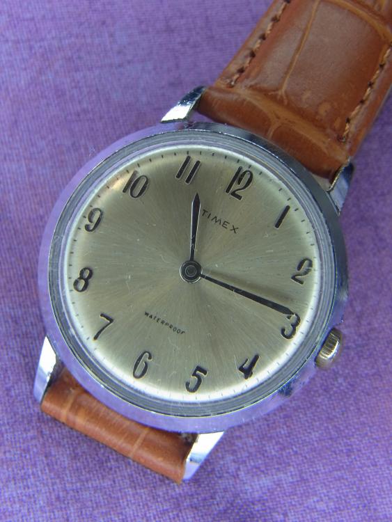
Now is the time to step back and chill out for a bit if you are feeling frustrated https://omegaforums.net/threads/sold-14k-solid-gold-omega-geneve-with-box.49223/ Is your watch constructed as this one? This one is in three parts: Snap on case back, case, and bezel. Bezel (which retains the crystal) should have a groove for a case opening tool, and with this off your dial and movement should come out handy.1 point
-
I personally doubt it is the click its more likely the automatic rotor. If it was me I would remove the auto rotor & test. It's just an elimination process.1 point
-
My opinion is "call a spade a spade" So let's call that watch what it is ... not an hommage but a replica. Nevertheless it's a watch and you need help. Those DG2813 movements seem to be hit or miss as some can work for years and some stop after some days If you want to replace it you could get a Miyota 2815, which is a direct swap as you can keep the dial and hands without modifying anything. But if you open the caseback and show us some close pics of the movement perhaps we could try to guess what's going wrong and if it is possible to repair. Envoyé de mon Moto G (5) Plus en utilisant Tapatalk1 point
-
If it was the click spring being too strong, is there anyway for me to lower the tension of the spring?1 point
-
Shouldn,t the movement be turned seveny eighty degrees with respect to the case, Some Omega do.1 point
-
Oh I forgot the wrist shot. Scratches at 8 and 11 o'clock are now gone. Where did all of that dust come from, it wasn't there two seconds before I took the shot.

 1 point
 -
You and old hippy wine the prize. It was a two stem watch and when I aligned to hike upward, I was able to lever the movement and with a pull it came out. I think Old Hippy also had the right technique, I was just a bit reluctant to pull on the crown.With no crystal. Sent from my iPhone using Tapatalk Pro1 point
-
Well the replacement fourth wheel finally arrived so I was able to compare it against the fourth wheel that was in the movement. Now I know the wheel I purchased is correct for the 1045 movement because it was still in it's original package (Omega Part #1045-1243) but to the naked eye (well, with the help of a loupe) both wheels looked exactly alike. This caused me a bit of concern since I was pretty darn sure the fourth wheel was the problem area. Counting gear teeth under the microscope the old wheel came in at 83 teeth and the new wheel at 84! Now we're getting somewhere! So I swapped out the wheels, reassembled the movement and let it run for a day- it's now just a minute fast per day and I should be able to regulate that out. Looking at the wheel to pinion tooth ratio I came up with the following- which obviously isn't correct so maybe someone can check my math! The movement beats at 28,800 bph. That's 8 beats per second. The escape wheel has 20 teeth on the wheel and 7 on the pinion. The correct fourth wheel has 84 teeth. If I figure there are 480 beats per minute (8 x 60 = 480), then divide that by the twenty teeth of the escape wheel (480/20 = 24), multiply the quotient by the number of teeth on the escape wheel pinion (24 x 7 = 168), and lastly divide that by the number of teeth on the fourth wheel (168/84 = 2) I end up with two revolutions of the fourth wheel for every 480 beats; clearly this isn't correct. The correct answer should be one revolution of the fourth wheel for every 480 beats. Somewhere I goofed up. If I run the same calculation using the old fourth wheel (83 teeth) I end up with 2.024096 revolutions per minute- which is clearly faster. At any rate the problem has been solved and the watch is finished. Thanks again for the input everyone.1 point
-
Nice clean movement.If it runs at all you should be able get it running well1 point
-
Got the new movement today and the good news was, it is a direct swap, just had to swap the datewheels as the new movement had a white datewheel and the Seiko Gen 2 has a black one. Simple enough to do. Swapped the 7T27 battery plate over with the original Seiko markings too All back together and working great!1 point
-
Not sure on which point you disagree but interchangeability was the corner stone of U.S. watchmaking. That said many of the movements have been massacred so maybe a jewel was replaced with the wrong one and the pivot adapted or a fork that was close mashed in somehow, etc. I've been across the pond a couple of decades but still see an American pw here and there. Last was a "maker" who recased old Elgins in wristwatch. Customer brought two of them for service (they were supposedly restored by the "maker"). Broken hs collet glued, escapement berzerked, dial glued on, balance pivots grooved, holes smashed closed, not untypical of stuff I saw regularly 20 years ago. But aside from maybe Howard or some of more boutique manufacturers no way they were hand fitting parts at Waltham Elgin Hamilton with the production numbers they were hitting. The finishing techniques for pivots for example may have been labor intensive but they were made to standards. The U.S. smacked the swiss so hard they had spies bringing back intel on manufacturing methods. Which they improved upon, and eventually smacked back with.1 point
-
I agree that this is his problem. he probably has a pivot or two of worn on one of the wheels . Unless it is a tooth of one of the wheels that is worn and that the watchmaker has not seen. It happens sometimes too1 point
-
I've seen this before and I agree with nickelsilver It's the teeth of the barrel mashing with the pinion of the center wheel. The watch I had somebody had substituted a different mainspring barrel and it was a very severe issue until I got a replacement barrel. Basically couldn't even time the watch at all.1 point
-
Somewhere in the discussion group within the last year or so this came up with another watch. So the balance wheel oscillates at its proper frequency the timing machine shows that. The gear ratio has to correspond to the rate of the balance wheel as pointed out above. If the gear ratio is wrong the hands will move at the wrong rate. I've seen this occur with several watches they came in several different frequencies. So basically physically identical watches a lot of parts would interchange except gear train they be some differences there for the gear ratio and the different balance wheels. This met when you're ordering replacement gear train gears you had the make sure you ordered the correct wheels or you'd get exactly what you have strange timekeeping.1 point
-
I think it's a gear ratio issue. A friend had a similar problem on a rolex 1570. He bought a spare part (in his case second wheel) on the internet. But the seller mixed parts of 1570 and 1530 which are very similar but have different numbers of teeth. So the wrong wheel fitted but established a wrong ratio. I would count the teeth on the wheels you replaced and compare that with the originals.1 point
-
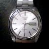
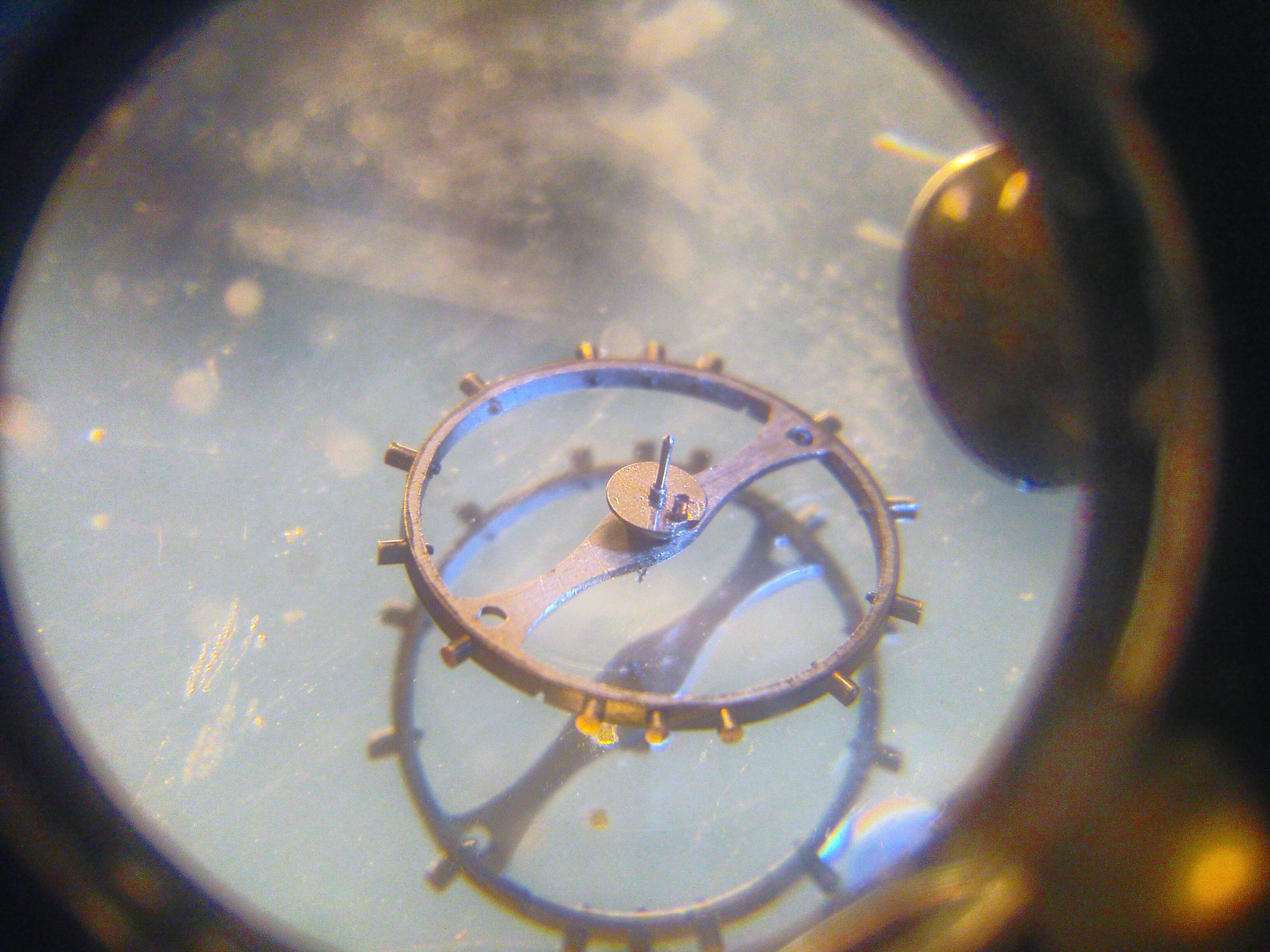
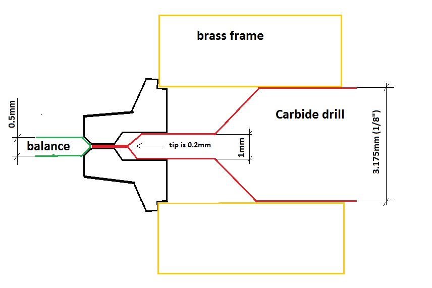
This balance was drilled but the bit was broken so o had to grind down the staff. Now it is drilled with 0.3mm drill and the pinion wire grinded from hss bit is fitted. The tool is motorized and fancy screws were made. With the adjustable puley wheel distance it is now totally safe for the drills. Now my question is how to measure the two endstonesdistance?

 1 point
 -
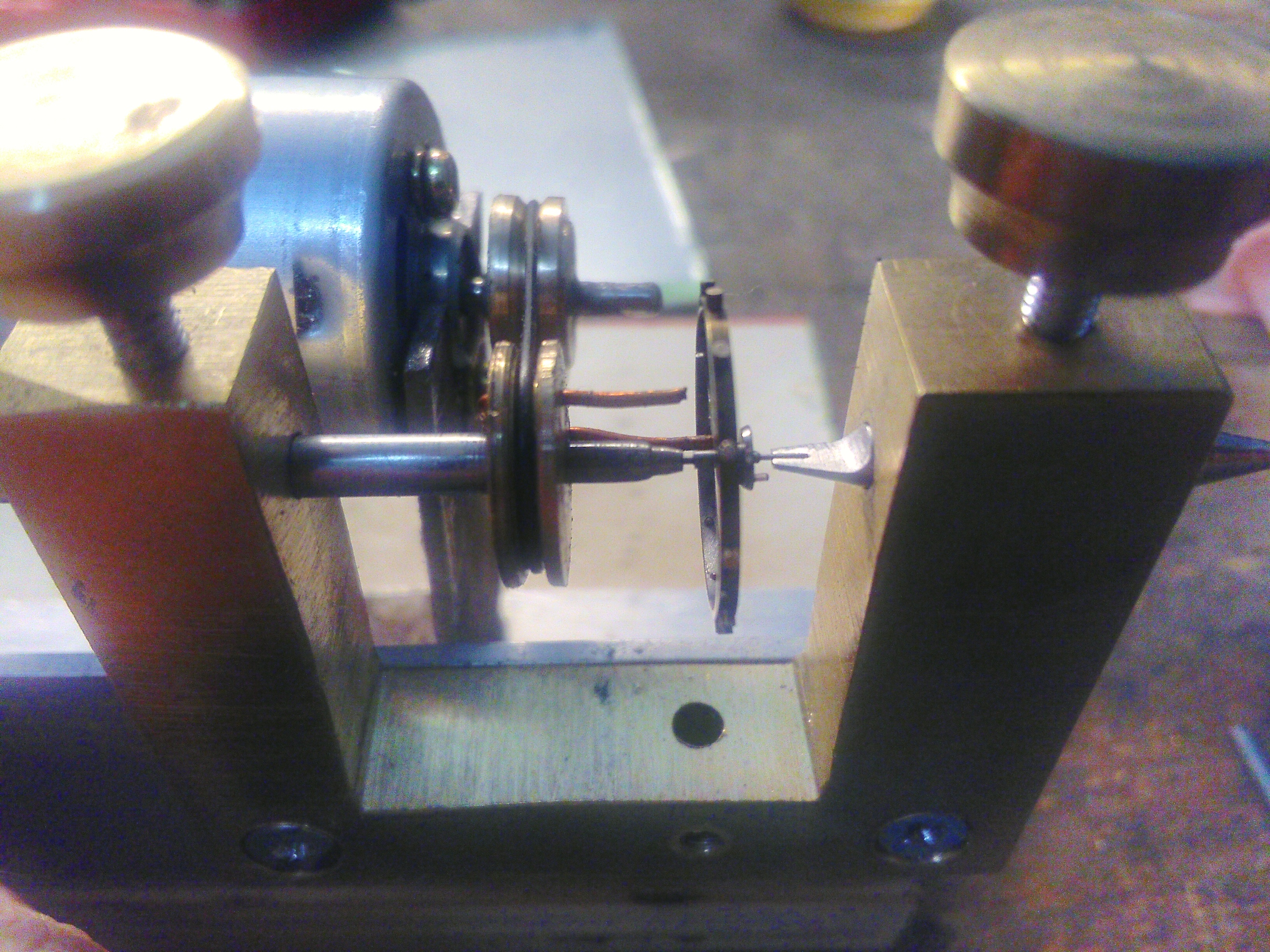
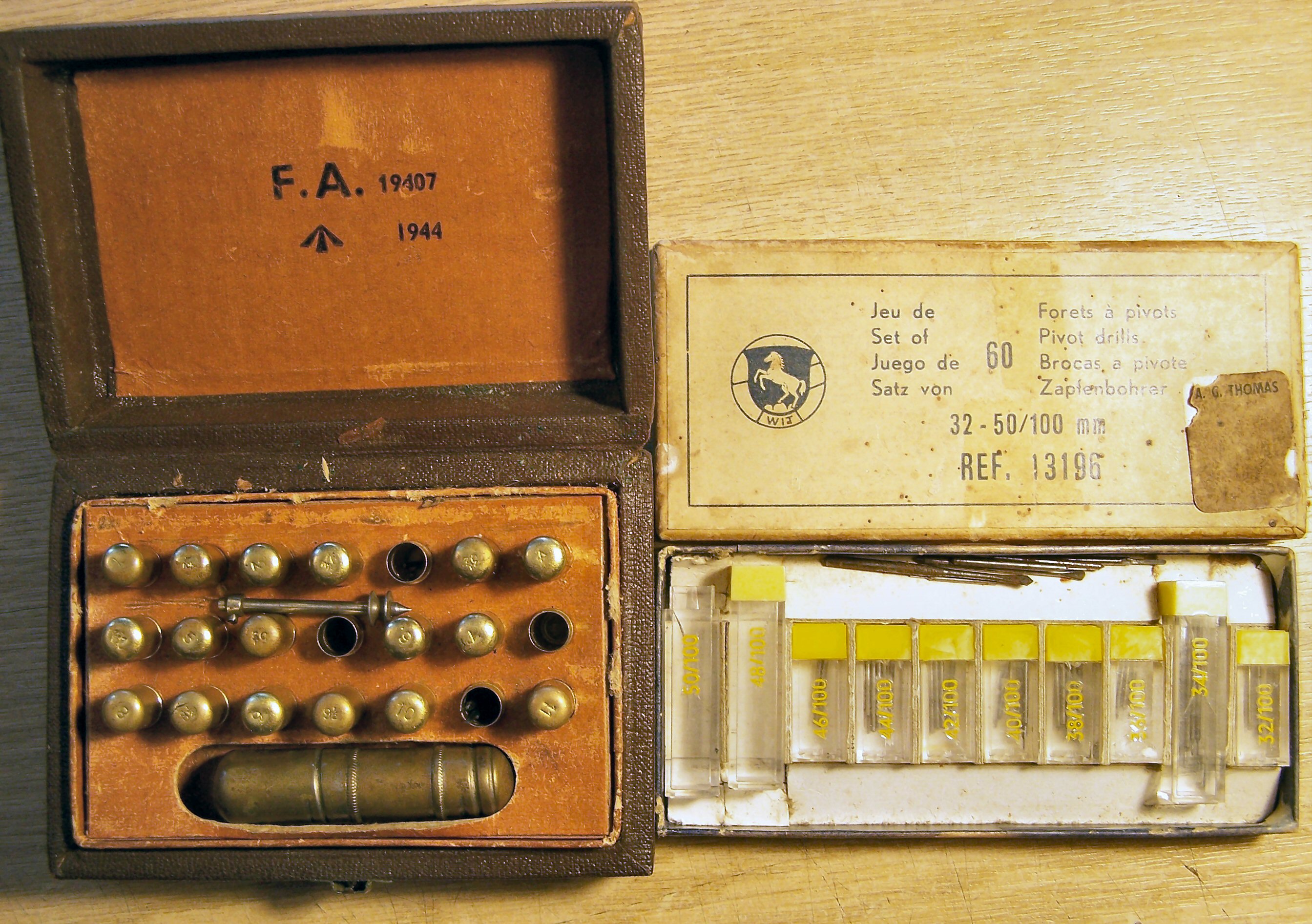
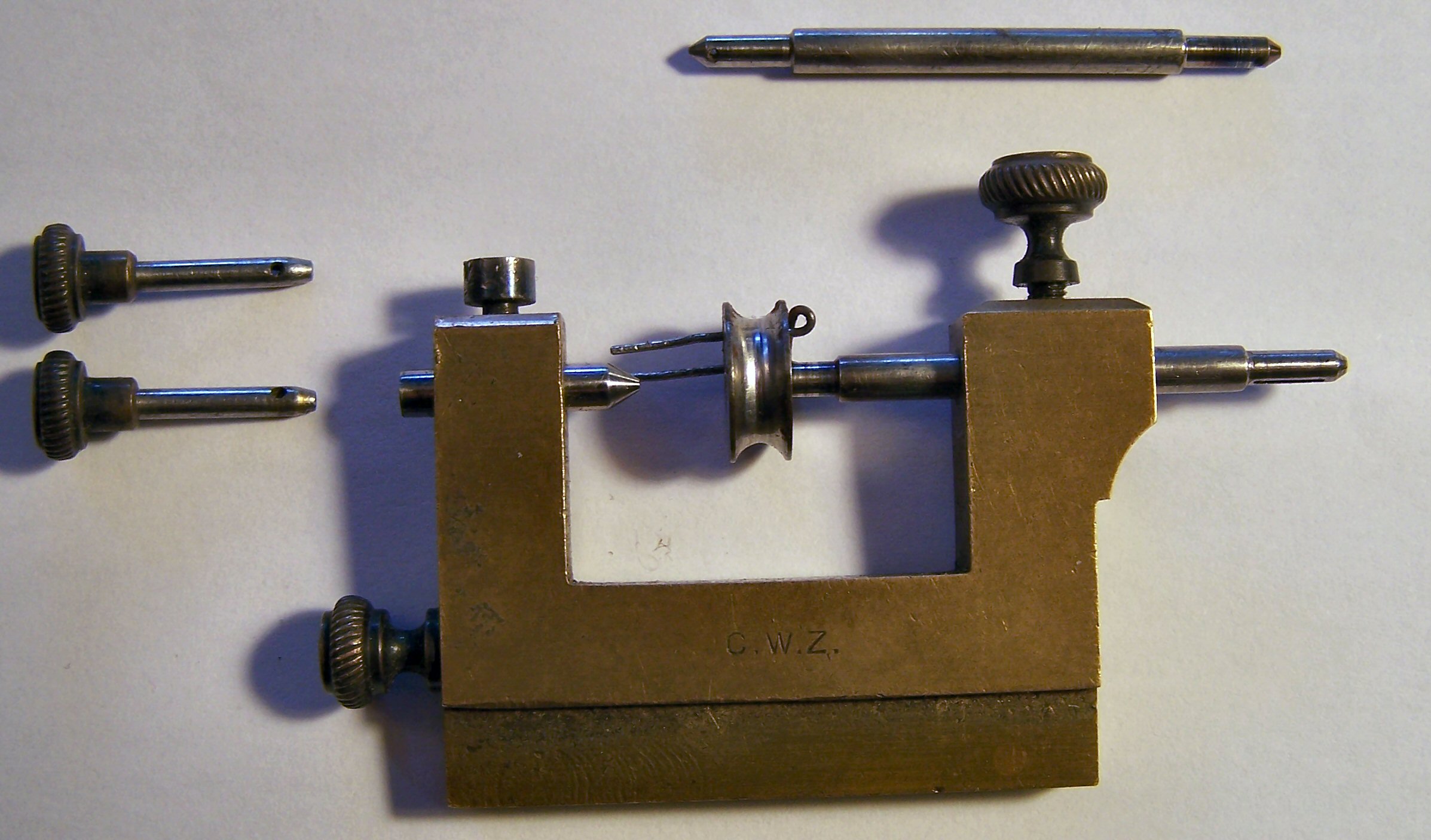
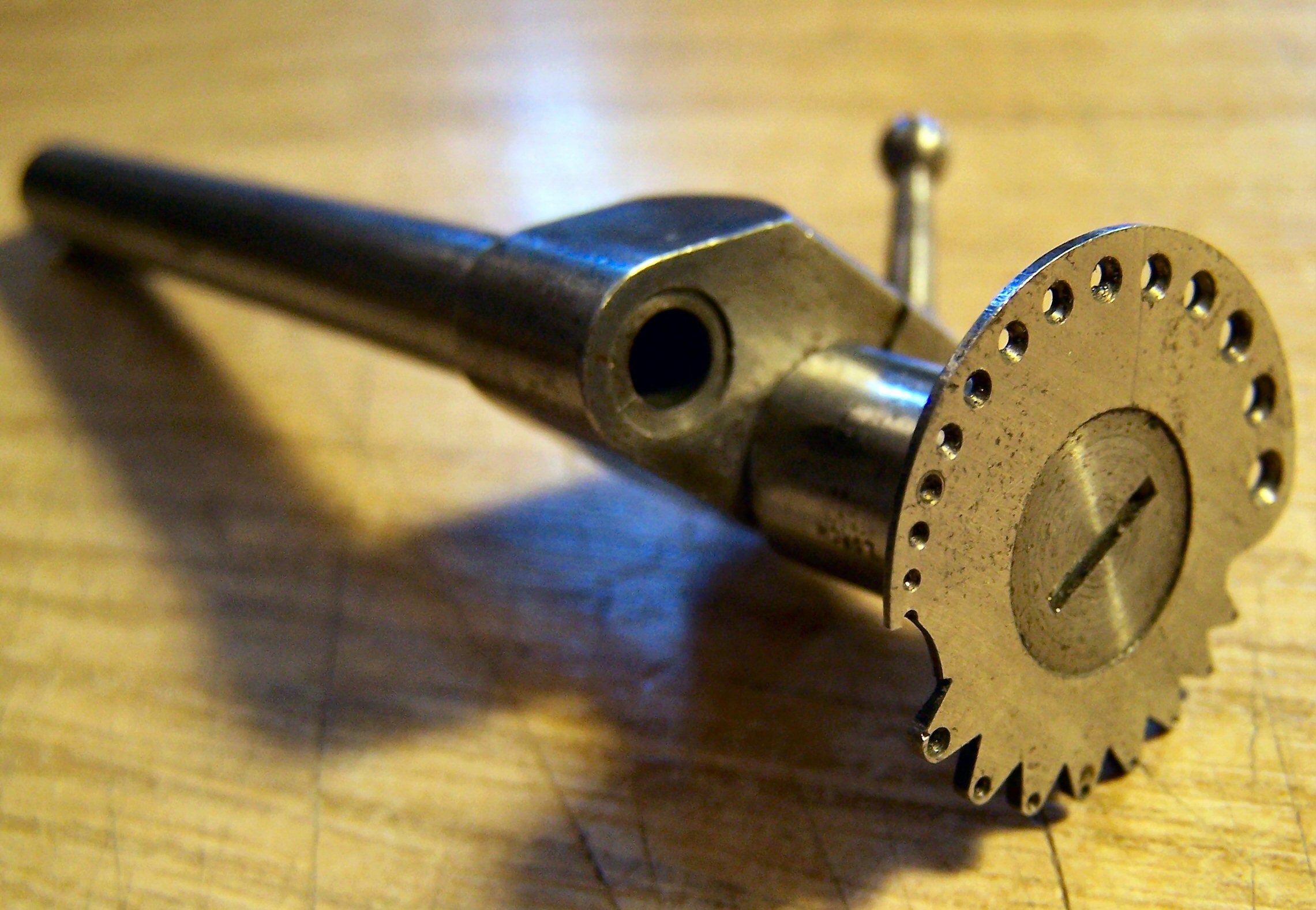
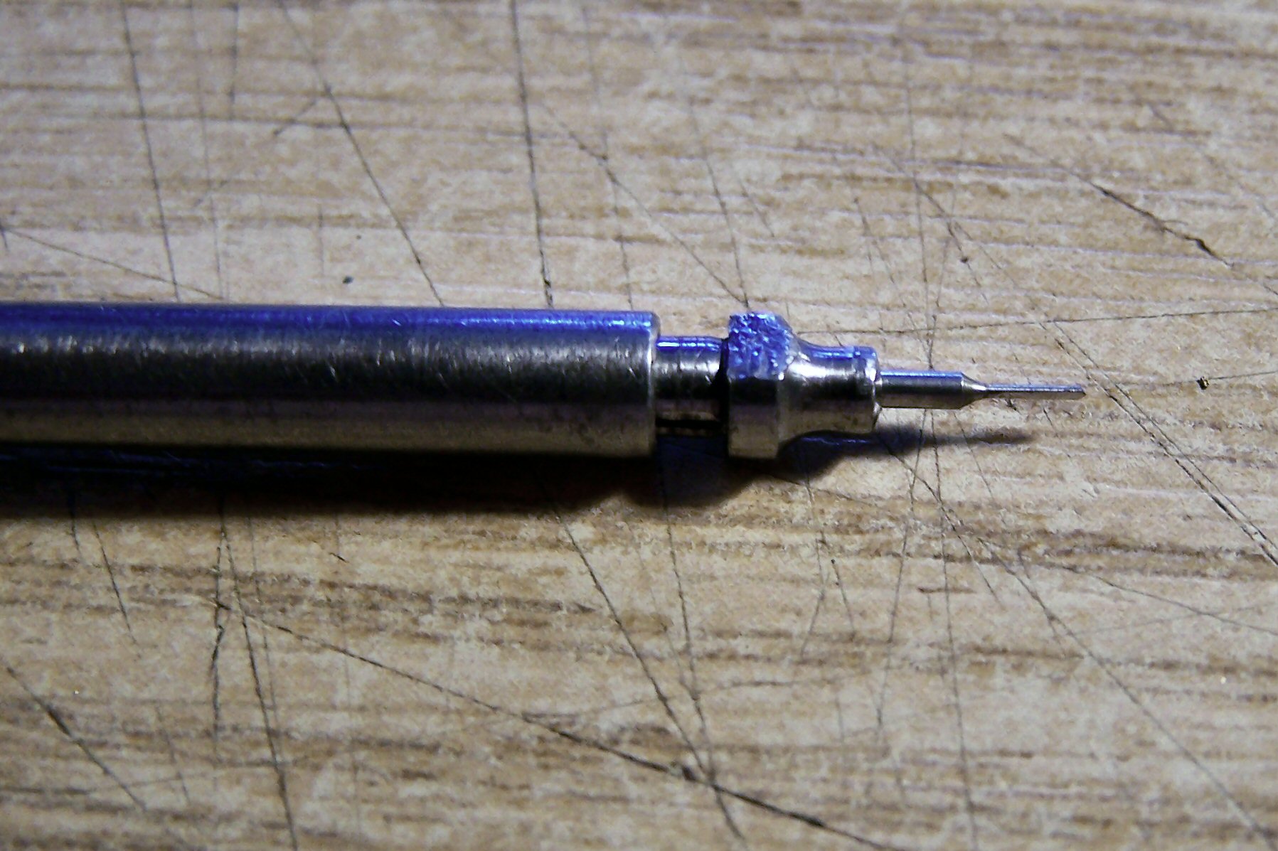
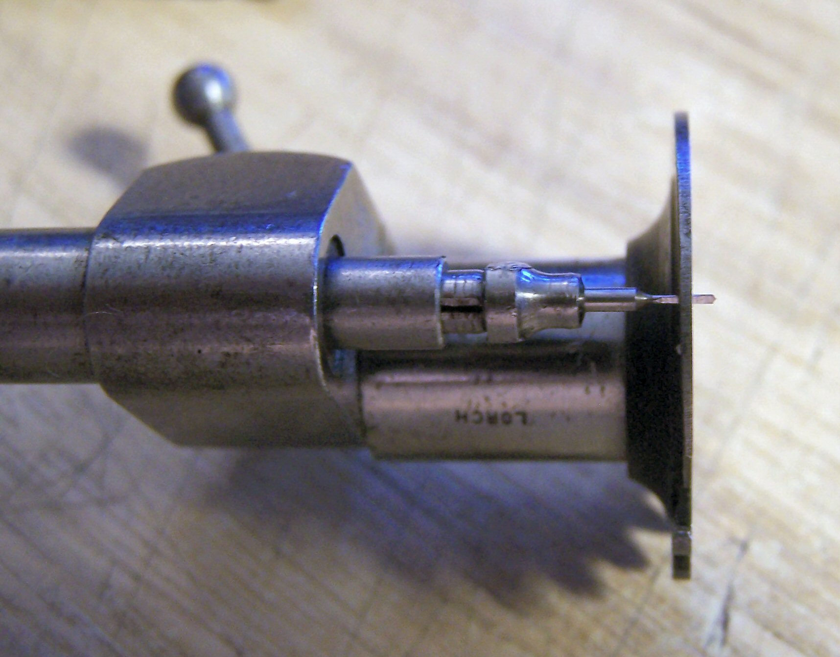
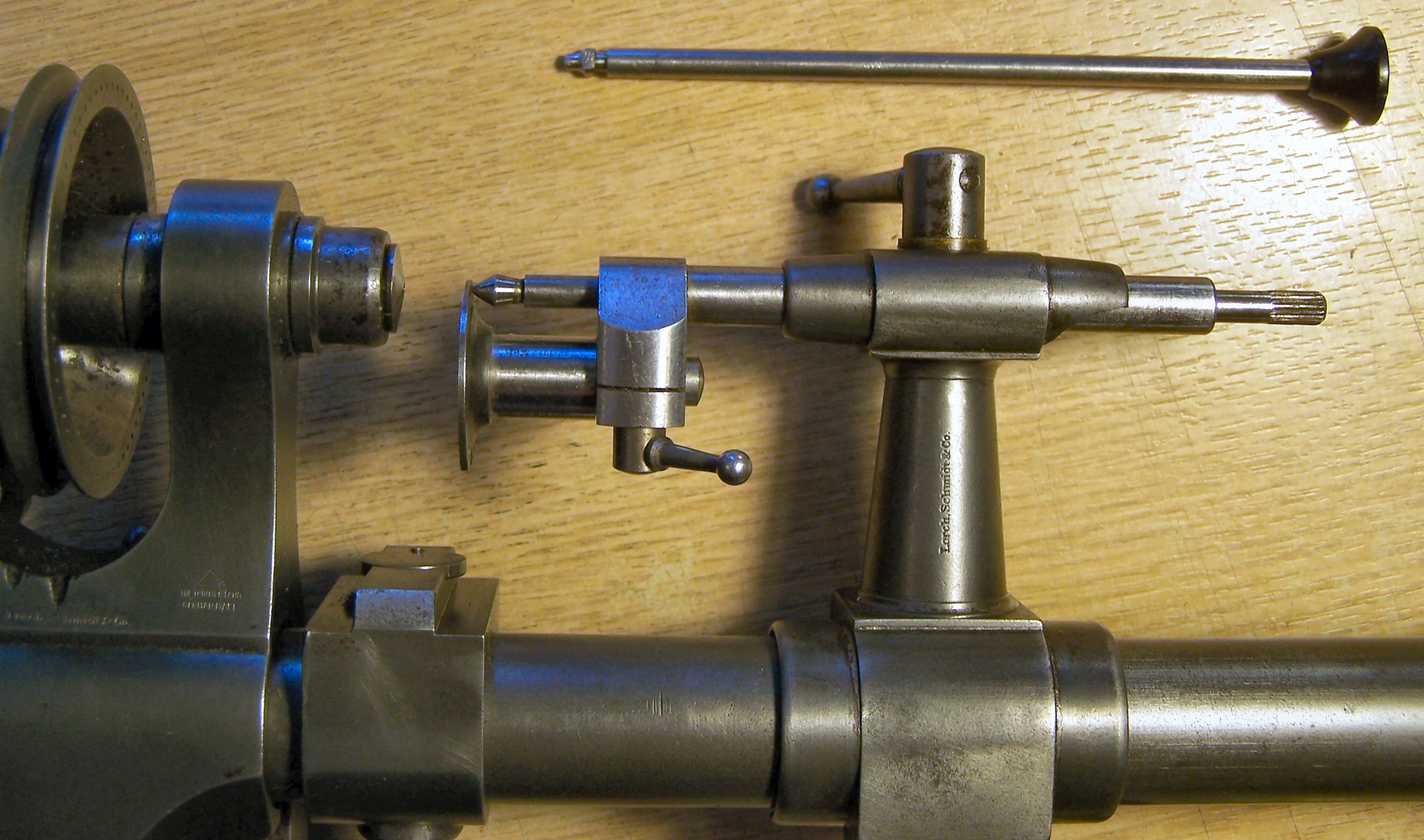
Here we go... The set comprises the tail stock attachment, an alignment tool, the drill holder, and 2 collets. This is the drill plate with a variety of different hole sizes, all with a conical profile so that the staff to be drilled stays aligned. a 0.42mm spade drill in the drilling rod. and how it fits through the back of the drill plate. All together on my 6mm Lorch Triumph with the alignment tool in place. I have not actually used this in anger as yet so I don't know how well things align between the head stock and the tail stock, but I would imagine that this set up is probably better used with a safety pulley type set up which would mean that you would be working between centres. I do have a safety pulley but it is for my BTM 8mm lathe, and this kit doesn't fit that. My lathe bits and pieces are somewhat eclectic as they have gradually been accuculated from a variety of sources and although the BTM is up and running, both lathes still need parts to get the best from them. And an assortment of drills which I think go down to 0.1mm and up to 1.1mm, although above 0.5mm they don't fit this rig. This is my other pivot drill. Almost exactly what SZB has built. Sadly I have no drills to fit this.


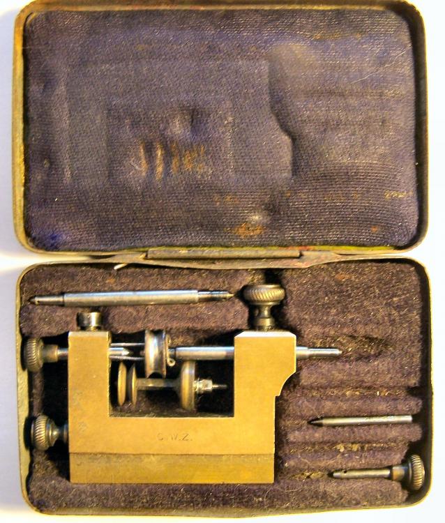

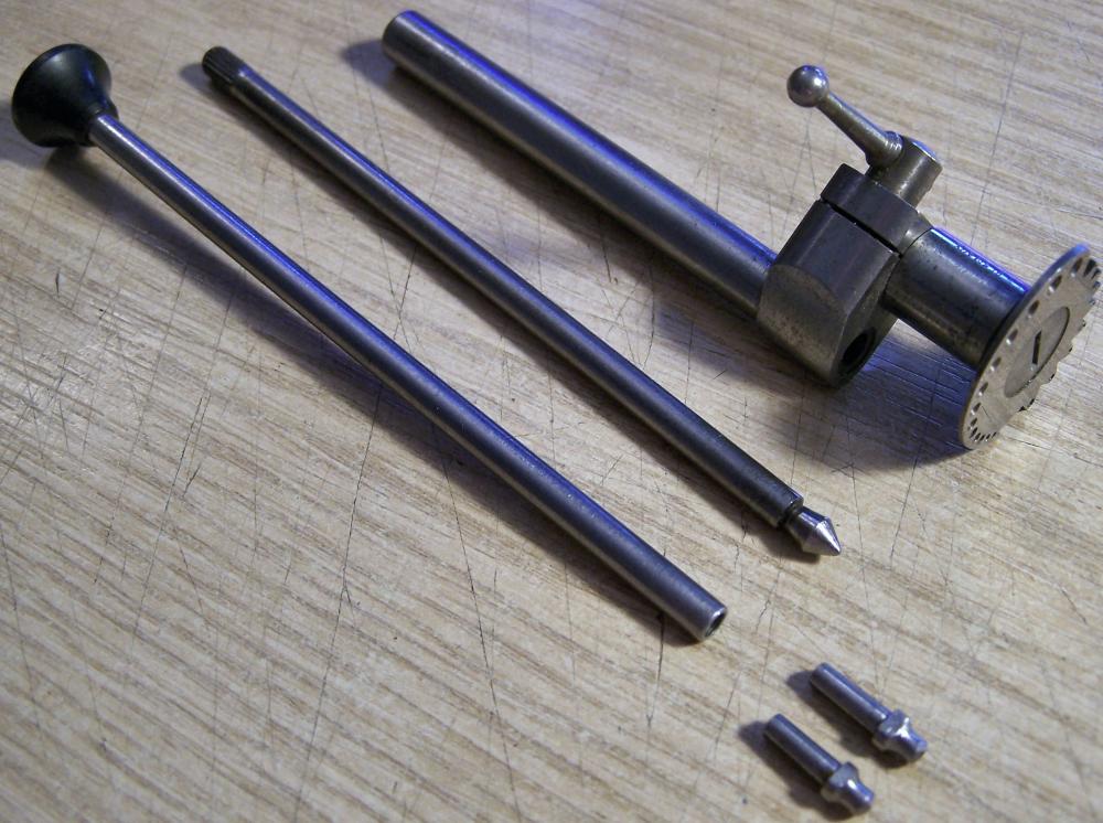

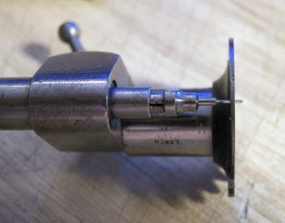
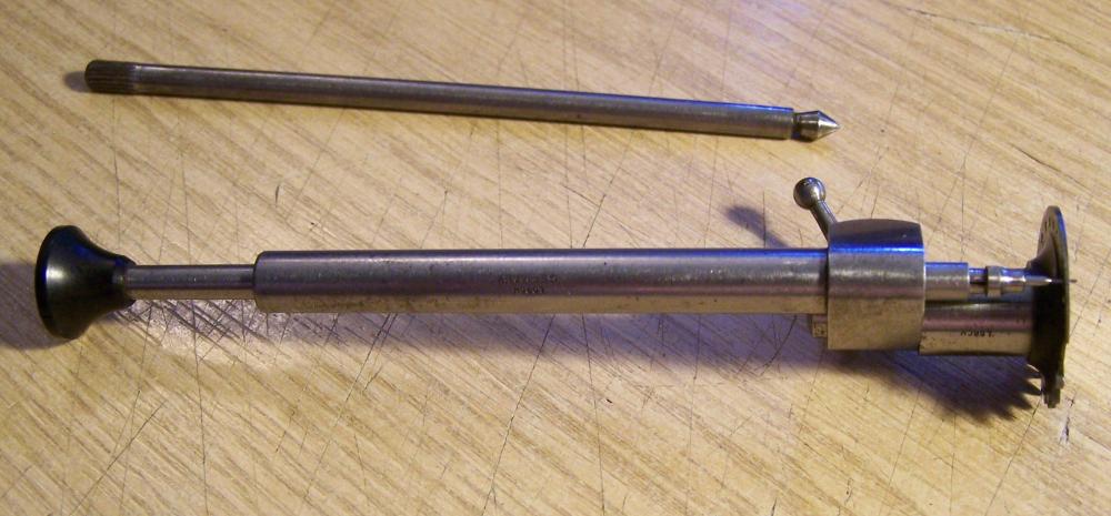
 1 point
 -
Lorch (and no doubt others) made a tailstock arrangement for their lathes which comprised a plate with a circle of varying sized conical holes which could be brought into alignment with the axis of the lathe, mounted onto a hollow shaft into which a drill holder could be inserted, specifically for re-pivoting work. I have one somewhere, will post a pic later.1 point
-
There is a tool which is specifically made for this job. I have seen them on the bay & I have always been outbid. I think I see a post where a guy made one but can not find it on the net just now, In theory you could do this with a watch makers lathe but i have not tried it.1 point
-
Balance drilling female cone to lead the drill perfectly centered:
 1 point